


ASUS P/I-XP6NP5 User’s Manual 9
III. INSTALLATION
III. INSTALLATION
(Jumpers)
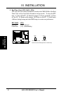
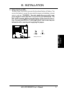
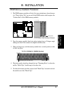
4. Battery Test Lead (JP7)
The Real Time Clock RAM is powered by the onboard button cell battery. You
can test the battery’s current by removing this jumper and attaching a current
meter to each pin. WARNING: You must unplug the power cord to your
power supply to ensure that there is no power to your motherboard. The
RTC RAM containing BIOS setup information will be cleared by this ac-
tion. You must enter BIOS to “Load Setup Defaults” and re-enter any user
information after removing and reapplying this jumper.
JP7
Battery Test Lead
Operation Test Mode
JP7