


ASUS P/I-XP6NP5 User’s Manual 5
III. INSTALLATION
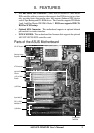
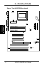
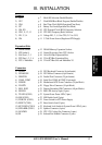
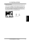
(Map of Board)
III. INSTALLATION
Jumpers
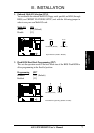
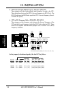
1) JP14 p. 7 Multi-I/O Selection (Enable/Disable)
2) JP17 p. 7 Flash ROM Boot Block Program (Enable/Disable)
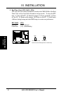
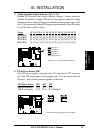
3) JP16 p. 8 Real Time Clock RAM (Operation/Clear Data)
4) JP7 p. 9 Battery Test Lead (Operation/Test Mode)
5) JP8, JP9 p. 10 CPU External Clock (BUS) Frequency Selection
6) JP10, 11, 12, 13 p. 10 CPU:BUS Frequency Ratio Selection
7) JP1, 2, 3, 4 p. 11 Voltage ID 3, 2, 1, 0 for CPU (2.1V to 3.5V)
8) JP6 p. 11 3.3Volt Power Source (Regulator/ATX Supply)
Expansion Slots
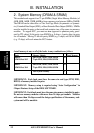
1) SIMM Sockets p. 12 DRAM Memory Expansion Sockets
2) ZIF Socket 8 p. 15 Central Processing Unit (CPU) Socket
3) ISA Slots 1, 2, 3 p. 16 16-bit ISA Bus Expansion Slots
4) PCI Slots 1, 2, 3, 4 p. 16 32-bit PCI Bus Expansion Slots
5) PCI 5 / MediaBus p. 18 32-bit PCI Bus Slot and MediaBus 2.0
Connectors
1) PS2KB p. 19 PS/2 Keyboard Connector (6-pin female)
2) PS2MOUSE p. 19 PS/2 Mouse Connector (6-pin female)
3) PRINTER p. 19 Parallel Port Connector (25-pin female)
4) COM1, COM2 p. 19 Serial Port COM1 & COM2 (9-pin male)
5) POWER p. 20 Motherboard ATX Power Connector (20-pin Block)
6) FLOPPY p. 20 Floppy Drive Connector (34-pin Block)
7) IDE1, IDE2 p. 21 Primary/Secondary IDE Connectors (40-pin Blocks)
8) IDELED p. 21 IDE LED Activity Light (2-pins)
9) TB LED (CON1) p. 22 System Power Power LED (2-pins)
10) SMI (CON1) p. 22 SMI Switch Lead (2-pins)
11) PWR SW. (CON1) p. 22 Power Switch for ATX Power Supply
12) RESET (CON1) p. 22 Reset Switch Lead (2-pins)
13) KEYLOCK (CON1) p. 22 Keyboard Lock Switch & System Power LED (5-pins)
14) SPEAKER (CON1) p. 23 Speaker Connector (4-pins)
15) FANPWR p. 24 CPU 12V Cooling Fan Connector (6-pins)
16) IR p. 24 Infrared Port Module Connector (5-pins)