


12 ASUS SP97 / SP97-V User’s Manual
III. INSTALLATION
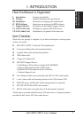
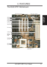
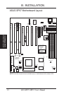
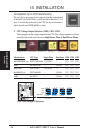
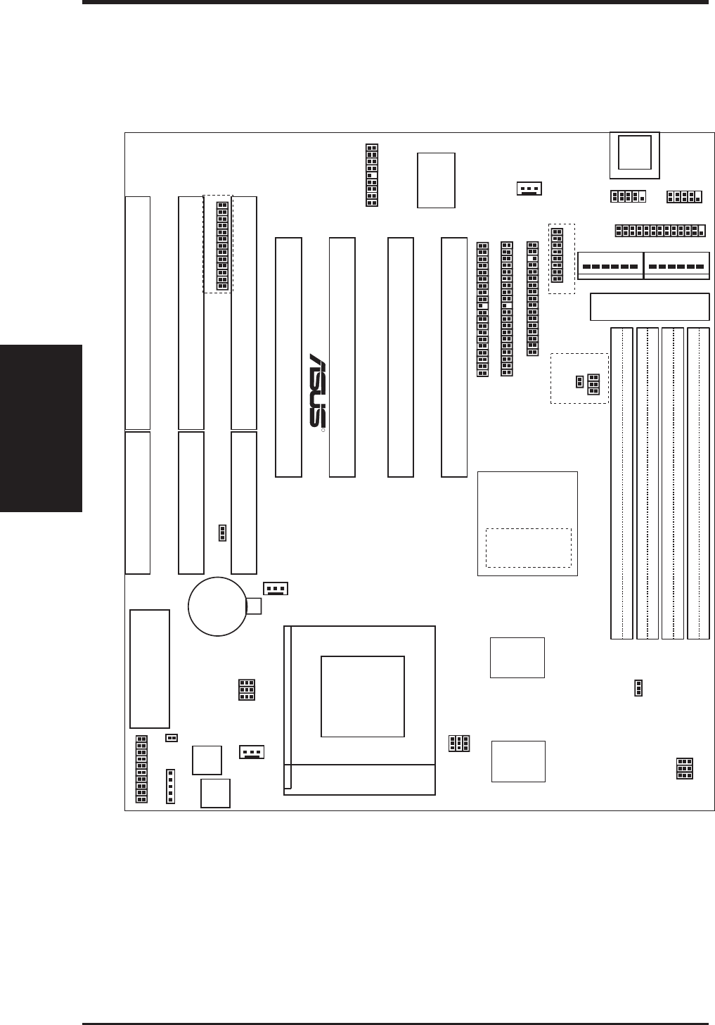
ASUS SP97 Motherboard Layout
(Motherboard Layout)
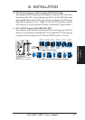
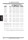
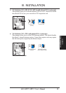
III. INSTALLATION
Power Fan
ATX Power Input
Secondary IDE
Primary IDE
Flash BIOS
USB, PS/2
Mouse, IrDA
IDE LED
Floppy Drives
Key-
board
Infrared
CPU Fan
ISA Slot 3
ISA Slot 2
ISA Slot 1
SIMM Socket 1 (32-bit, 72-pin module)
SIMM Socket 2 (32-bit, 72-pin module)
SIMM Socket 3 (32-bit, 72-pin module)
SIMM Socket 4 (32-bit, 72-pin module)
01
23 23
Row
01
CPU ZIF Socket 7
AT Power Input
P8
P9
Parallel Port
Serial Ports
COM 2
COM 1
Super
Multi-I/O
SiS 5582
Chipset
or
SiS 5598
Chipset
CR2032 3Volts
Lithium Cell
BIOS Power
CPU Voltage
VID0
VID1
VID2
Freq. Ratio
BF0
BF1
Panel Connectors
Clock Freq.
FS3
Clock Freq
FS1
FS2
FS0
Switching
Voltage
Regulators
512KB/256KB Pipelined Burst L2 Cache
Feature Connector
VGA Connector
VGA
Select
VGA
Select 1
NOTE: Outlined components are available only on motherboards with onboard VGA.
Chassis Fan
BF2
RTC Clear / Battery Test
PCI Slot 1
PCI Slot 2
PCI Slot 3
PCI Slot 4
R