


20
Chapter 1: System introduction
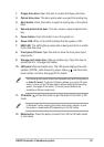
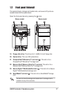
8. Parallel port. This 25-pin port connects a printer, scanner, or other
devices.
9. Line Out port. This Line Out (lime) port connects a headphone or a
speaker. In 4/6-channel mode, the function of this port becomes Front
Speaker Out.
10. Line In port. This Line In (light blue) port connects a tape player or
other audio sources. In 6-channel mode, the function of this port
becomes Low Frequency Enhanced Output/Center.
11. Microphone port. This Microphone (pink) port connects a
microphone. In 4/6-channel mode, the function of this port becomes
Surround Speaker.
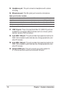
12. USB 2.0 ports. These Universal Serial Bus 2.0 (USB 2.0) ports are
available for connecting USB 2.0 devices such as a mouse, printer,
scanner, camera, PDA, and others.
13. Ethernet LAN port. This port allows connection to a Local Area
Network (LAN) through a network hub.
14. AGP slot cover. Remove this cover when installing an AGP card.
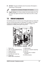
15. Chassis fan. This fan provides ventilation inside the system chassis.
16. Radio antenna port. This port connects an optional radio antenna.
17. Power supply unit fan. This fan provides ventilation inside the
power supply unit.
18. Power socket. This socket connects the power cable and plug.
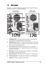
19. Voltage selector. This switch allows you to select the appropriate
voltage supply in your area. See the “Voltage selector” section on
page 40 before adjusting this switch.
20. Expansion card lock. This metal lock secures installed expansion
cards. See page 33 for details.
21. Video In port. (Deluxe models-Consumer edition only.) This port
connects a video casette recorder.
22. Cable TV connector. (Deluxe models-Consumer edition only.) This
connects a cable TV twist-on connector.
23. Wireless LAN adapter antenna connector. This connects the
dipolar antenna of the wireless LAN adapter.
24. Link LED. This yellow LED lights up when the wireless LAN adapter
radfio is on but has no activity.