


2-18
Chapter 2: Basic installation
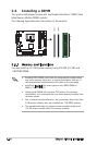
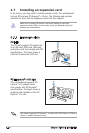
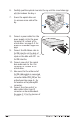
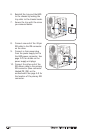
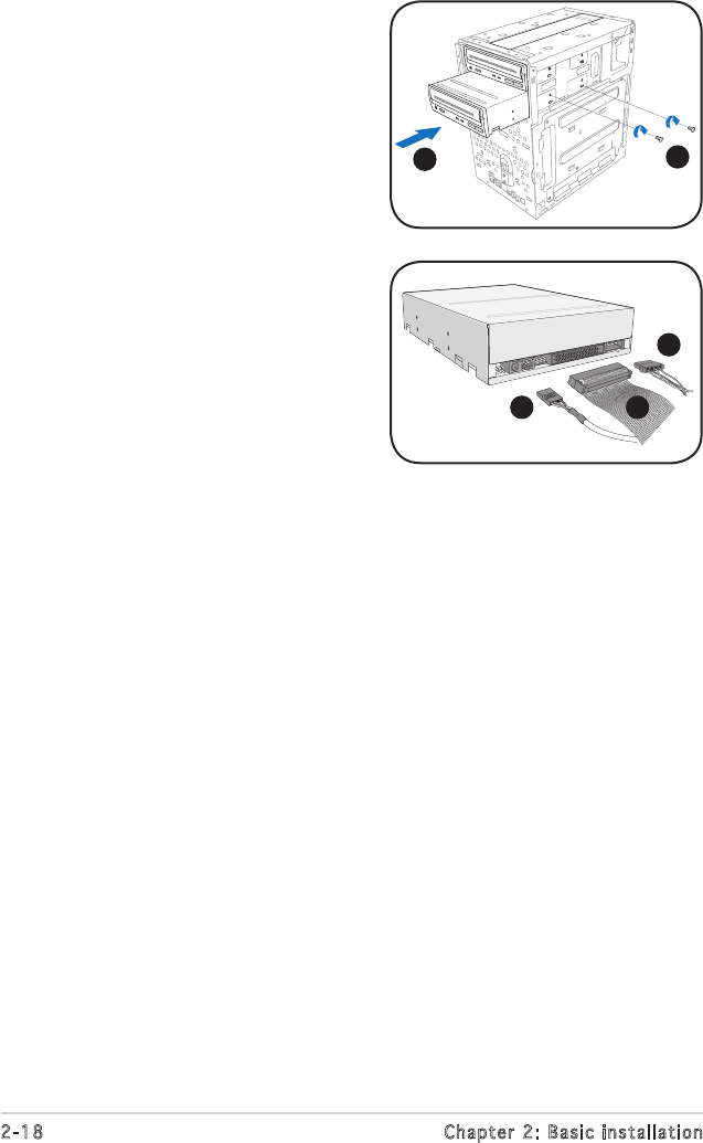
6. Carefully push the optical drive into the bay until its screw holes align
with the holes on the bay as
shown.
7. Secure the optical drive with
two screws on one side of the
bay.
6
7
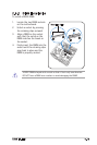
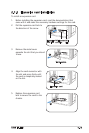
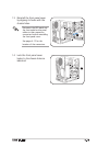
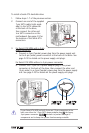
8. Connect a power cable from the
power supply unit to the power
connector at the back of the
optical drive. See page 2-25 for
details on the power supply unit
plugs.
9. Connect the IDE ribbon cable to
the IDE interface at the back of
the optical drive, matching the red
stripe on the cable with Pin 1 on
the IDE interface.
10. Connect one end of the optical
drive audio cable to the 4-pin
connector at the back of the
optical drive.
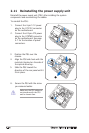
11. Make sure that the other end of
the IDE ribbon cable is connected
to the primary IDE connector (blue
connector labeled PRI_IDE) on the
motherboard. See page 4-8 for
the location of the primary IDE
connector.
12. Connect the other end of the
audio cable to the 4-pin CD
connector on the motherboard.
See page 4-10 for the location of
the CD audio connector.
8
9
10