


4-12
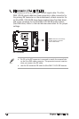
Chapter 3: Starting up
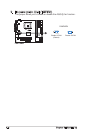
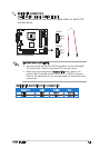
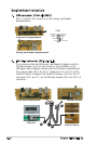
1. USB connector (10-1 pin USB1)
Pins 1~5 are for the connector on the storage card reader
daughterboard.
USB1
USB Power
USBP2
–
USBP2
+
GND
+5V
Power Botto
n
USB Powe
r
USBP1
–
USBP1
+
GND
NC
Front panel daughterboard
Storage card reader daughterboard
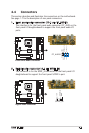
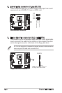
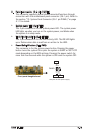
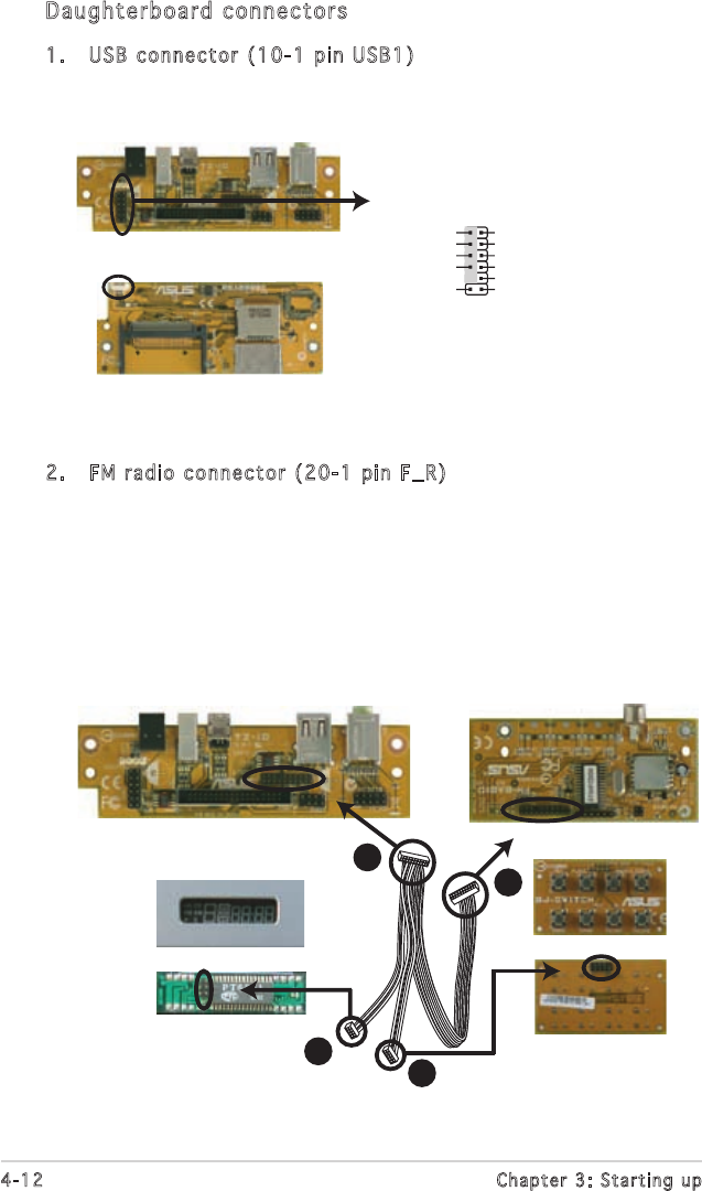
2. FM radio connector (20-1 pin F_R)
This connector links the LED panel, the Adudio DJ Switch, and the
FM radio module. (A) is for the connector (6 pin PANEL) on the
LED panel, which displays various system information, depending on
the system mode. (B) is for the J1 connector (10-1 pin J1) on the
Audio DJ Switch to support the Audio DJ buttons. (C) is for the J11
connector (20-1 pin J11) on the FM radio module. (D) is for the F_R
connector.
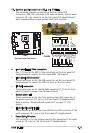
Front panel daughterboard
FM Radio module
Audio DJ Switch
LED panel
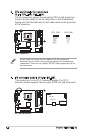
(Reverse)
(Reverse)
(Obverse)
(Obverse)
A
B
C
D
Daughterboard connectors