


24 ASUS TRL-DLS User’s Manual
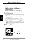
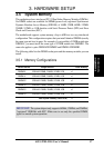
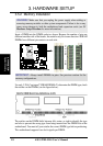
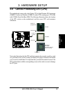
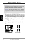
3. HARDWARE SETUP
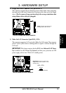
Connectors
3. H/W SETUP
3.8 Connectors
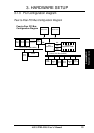
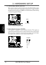
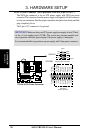
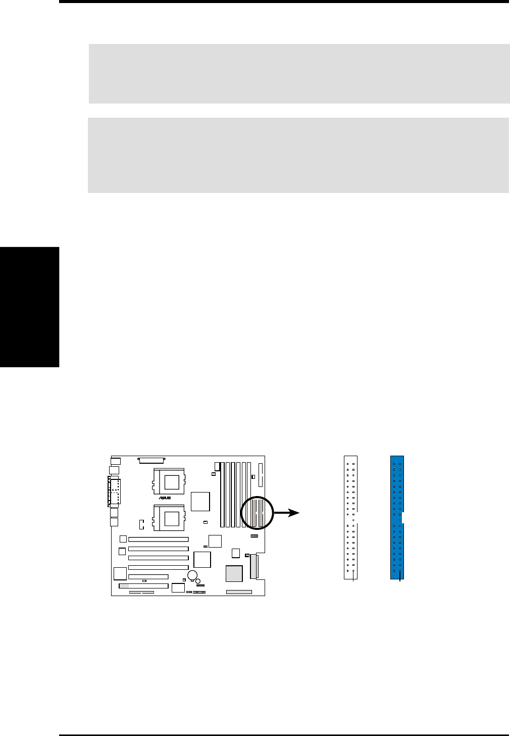
1) IDE Connectors (40-1 pin PRIMARY/SECONDARY)
These connectors support ATA-100 IDE hard disks. Use IDE ribbon cables to
connect the master and slave devices to these connectors. If you install two hard
disks, you must configure the second drive as a slave device by setting its jumper
accordingly. Refer to the hard disk documentation for the jumper settings. BIOS
supports specific device bootup (see 4.6. Boot Menu).
NOTE: Pin 20 on each IDE connector is removed to match the covered hole
on the ATA-100 cable connector. This prevents incorrect orientation when
you connect the cables.
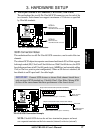
TIP: You may configure two hard disks to be both Masters with two ribbon
cables – one for the primary IDE connector and another for the secondary
IDE connector.
IMPORTANT: Always connect ribbon cables such that the red stripe matches
Pin 1 on the connector. Pin 1 is usually on the side closest to the power connector
on hard disk drives and CD-ROM drives, but may be on the opposite side on
floppy disk drives.
WARNING! Some pins are used for connectors or power sources. These are
clearly distinguished from jumpers in the Motherboard Layout. Placing jumper
caps over these connector pins will cause damage to your motherboard.
TRL-DLS
®
TRL-DLS IDE Connectors
NOTE: Orient the red markings
(usually zigzag) on the IDE
ribbon cable to PIN 1.
Secondary IDE Connector
Primary IDE Connector
PIN 1PIN 1