


32
3. HARDWARE SETUP
ASUS TRL-DLS User’s Manual
3. H/W SETUP
Connectors
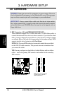
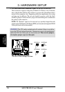
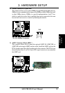
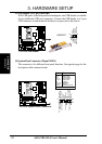
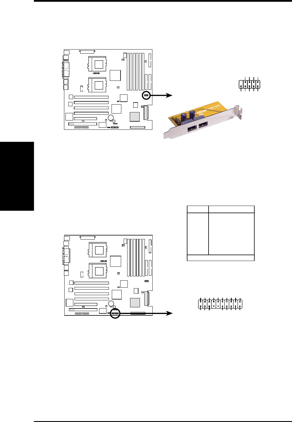
13) USB Header (10-1 pin USBPORT)
If the USB ports at the back panel are inadequate, one USB header is available
for two additional USB port connectors. Connect the USB header to a 2-port
USB connector set and mount the bracket to an open slot in the chassis.
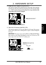
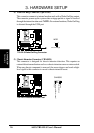
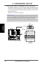
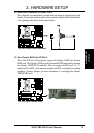
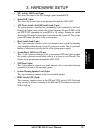
14) System Panel Connector (20-pin PANEL)
This connector is for different front panel functions. See opposite page for the
description of the connector leads.
TRL-DLS
®
TRL-DLS USB Header
USBPORT
NC
GND
USBP2+
USBP2–
USB Power
GND
USBP3+
USBP3–
USB Power
15
610
TRL-DLS
®
TRL-DLS System Panel Connectors
Pin Connector
1 & 12 NIC Activity LED
2 & 3 Status LED
6 & 7 Power Switch
9 & 10 Reset Switch
11 & 13 Power LED
14 Keylock
15* & 16 NMI Button
17 & 20 Speaker
18 & 19 HDD Access LED
* Shared
GND
NIC activity LED+
Power LED +
HDD access LED–
Status LED –
Status LED+
RESET button
GND
+5V
HDD access LED+
Power LED –
GND
Speaker
NIC activity LED–
Power Switch
110
11 20
NMI button
Keylock