


28
3. HARDWARE SETUP
ASUS TRL-DLS User’s Manual
3. H/W SETUP
Connectors
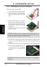
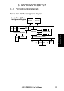
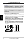
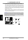
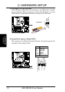
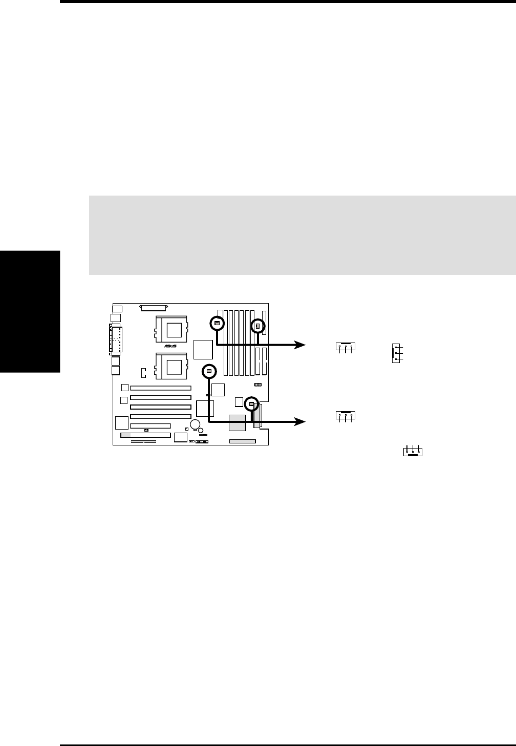
7) CPU and Chassis Fan Connectors (3-pin CPUFAN1/2, SYSFAN1/2)
These connectors support cooling fans of 860mA (10.3 Watts) or less. Orient the
fans so that the heat sink fins allow airflow to go across the onboard heat sink(s)
instead of the expansion slots. Depending on the fan manufacturer, the wiring
and plug may be different. The red wire should be positive, while the black
should be ground. Connect the fan’s plug to the board taking into consideration
the polarity of the connector.
NOTE: The “Rotation” signal is to be used only by a specially designed fan with
rotation signal. The Rotations Per Minute (RPM) can be monitored using Intel LDSM
Utility (provided with certain models).
WARNING! The CPU and/or motherboard will overheat if there is no airflow
across the CPU and onboard heatsinks. Damage may occur to the motherboard
and/or the CPU fan if these pins are incorrectly used. These are not jumpers,
do not place jumper caps over these pins.
TRL-DLS
®
TRL-DLS 12-Volt Cooling Fan Power
GND
Rotation
+12V
SYSFAN2
SYSFAN1
GND
Rotation
+12V
CPUFAN2
GND
Rotation
+12V
GND
Rotation
+12V
CPUFAN1