


12 ASUS TXP4 User’s Manual
III. INSTALLATION
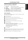
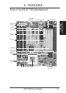
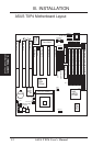
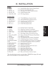
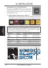
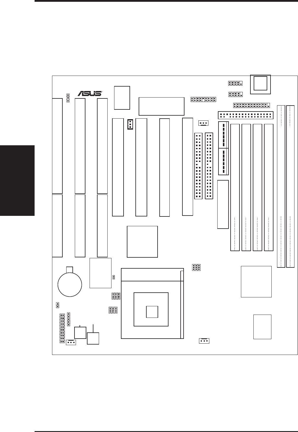
ASUS TXP4 Motherboard Layout
(Motherboard Layout)
III. INSTALLATION
R
Panel Connectors
Infrared
RTC Clear
Boot Block Write
COM 2
COM 1
IDE LED
Chassis
Fan
Switching Voltage
Regulators
Freq. Ratio
01
01 23 23
Row
10
32
Row
P8
P9
BF1
BF0
BF2
VID1
VID0
VID2
CPU Voltage
Clock Freq
FS1
FS0
FS2
CPU Fan
Power Fan
Wake on LAN
BIOS Power
CR2032 3V
Lithium Cell
Serial Ports
Floppy Drives
Secondary IDE
Primary IDE
PS/2 Mouse,
USB, IrDA
Parallel (Printer) Port
ISA Slot 1
ISA Slot 2
ISA Slot 3
PCI Slot 1
PCI Slot 2
PCI Slot 3
PCI Slot 4
Intel
PIIX4
PCIset
Intel
430TX
PCIset
SIMM Socket 4 (32-bit, 72-pin module)
SIMM Socket 3 (32-bit, 72-pin module)
SIMM Socket 2 (32-bit, 72-pin module)
SIMM Socket 1 (32-bit, 72-pin module)
DIMM Socket 1 (64-bit, 168-pin module)
DIMM Socket 2 (64-bit, 168-pin module)
Flash BIOS
Super
Multi-I/O
ASUS
ASIC
CPU ZIF Socket 7
512KB PB
L2 Cache
ATX Power Input
AT Power Input
Key-
board