


1-8
Chapter 1: Product introduction
Chapter 1
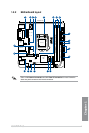
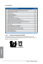
Layout contents
Connectors/Jumpers/Slots/LEDs
Page
1. CPU and chassis fan connectors (4-pin CPU_FAN, 4-pin CHA_FAN1/2) 1-17
2. ATX power connectors (24-pin EATXPWR, 8-pin EATX12V)
1-19
3. TPM header (20-1 pin TPM) 1-19
4. MemOK! button 1-13
5. LGA1150 CPU socket 1-8
6. DRAM LED (DRAM_LED) 1-14
7. DDR3 DIMM slots 1-9
8. Standby power LED (SB_PWR) 1-14
9. Speaker connector (4-pin SPEAKER) 1-17
10. System panel connector (10-1 pin F_PANEL) 1-20
11. Intel
®
Z97 Serial ATA 6.0 Gb/s connectors (7-pin SATA6G_1-4) 1-15
12. USB 3.0 connector (20-1 pin USB3_12) 1-16
13. M.2 Socket 3 1-18
14. USB 2.0 connector (10-1 pin USB1112) 1-16
15. Clear CMOS header (2-pin CLRTC) 1-12
16. Digital audio connector (4-1 pin SPDIF_OUT) 1-15
17. Front panel audio connector (10-1 pin AAFP) 1-18
18. WiFi LED (WIFI_LED) 1-14
19. Bluetooth LED (BT_LED) 1-14
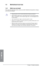
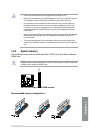
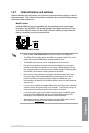
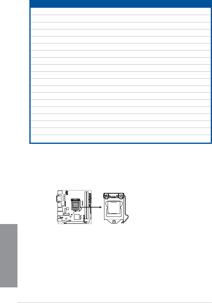
1.2.3 Central Processing Unit (CPU)
The motherboard comes with a surface mount LGA1150 socket designed for the 4th
Generation, New 4th Generation and 5th Generation Intel
®
Core™ i7 / Core™ i5 / Core™ i3,
Pentium™, and Celeron™ processors.
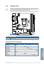
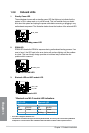
Z97I-PLUS
Z97I-PLUS CPU socket LGA1150