


ASUS Z97I-PLUS
1-17
Chapter 1
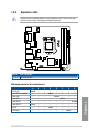
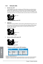
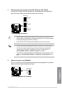
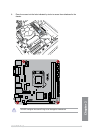
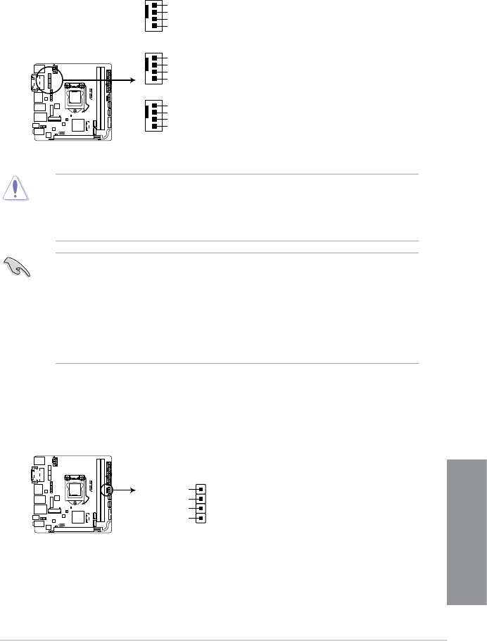
5. CPU and chassis fan connectors (4-pin CPU_FAN; 4-pin CHA_FAN1/2)
Connect the fan cables to the fan connectors on the motherboard, ensuring that the
black wire of each cable matches the ground pin of the connector.
• DO NOT forget to connect the fan cables to the fan connectors. Insufcient air ow
inside the system may damage the motherboard components. These are not jumpers!
Do not place jumper caps on the fan connectors!
• Ensure that the CPU fan cable is securely installed to the CPU fan connector.
• The CPU_FAN connector supports the CPU fan of maximum 1A (12 W) fan power.
• The CPU fan connector detects the type of CPU fan installed and automatically
switches the control modes. To congure the CPU fan’s control mode, go to
Advanced Mode > Monitor > CPU Q-Fan Control item in BIOS.
• The chassis fan connectors support DC and PWM modes. To set these fans to DC or
PWM, go to Advanced Mode > Monitor > Chassis Fan 1/2 Q-Fan Control items in
BIOS.
Z97I-PLUS
Z97I-PLUS Fan connectors
CHA_FAN2
GND
CHA FAN PWR
CHA FAN IN
+5V
CHA_FAN1
GND
CHA FAN PWR
CHA FAN IN
+5V
CPU_FAN
GND
CPU FAN PWR
CPU FAN IN
CPU FAN PWM
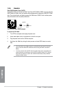
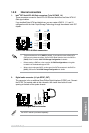
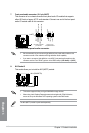
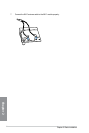
6. Speaker connector (4- pin SPEAKER)
This 4-pin connector is for the chassis-mounted system warning speaker. The speaker
allows you to hear system beeps and warnings.
Z97I-PLUS
Z97I-PLUS Speaker out connector
Speaker Out
GND
GND
+5V
SPEAKER
PIN 1