


1-20
Chapter 1: Product introduction
Chapter 1
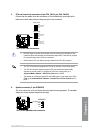
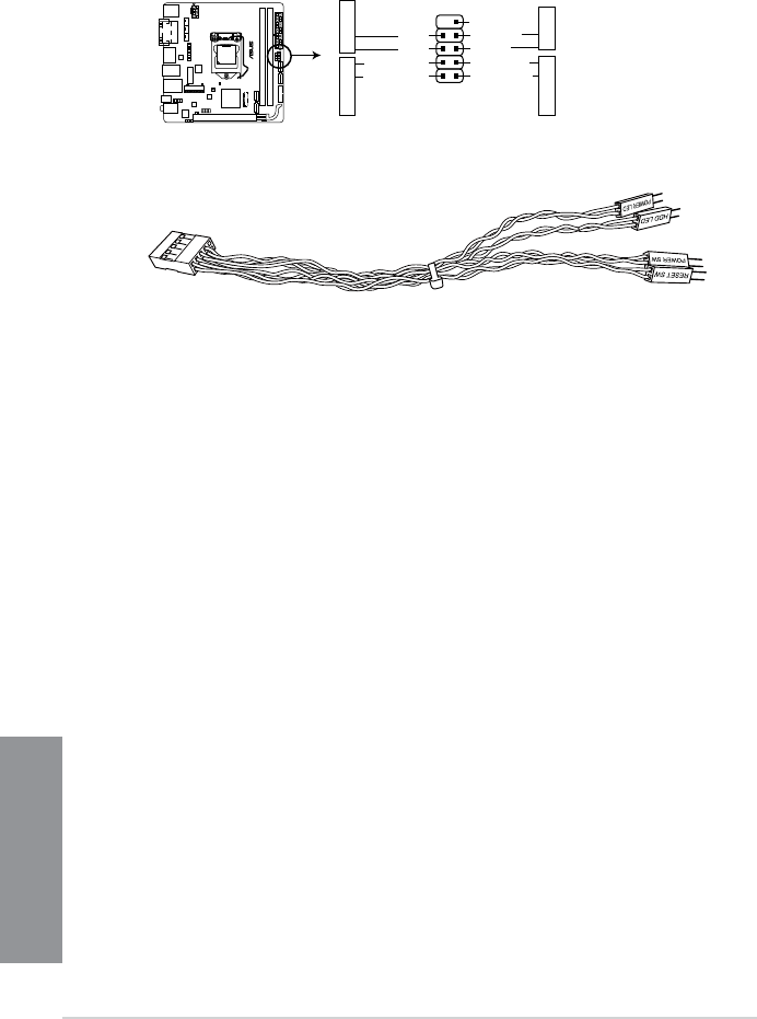
• SystempowerLED(2-pin+PWR_LED-)
This 2-pin connector is for the system power LED. Connect the chassis power LED
cable to this connector. The system power LED lights up when you turn on the system
power, and blinks when the system is in sleep mode.
• HarddiskdriveactivityLED(2-pin+HDD_LED-)
This 2-pin connector is for the HDD Activity LED. Connect the HDD Activity LED cable
to this connector. The HDD LED lights up or ashes when data is read from or written
to the HDD.
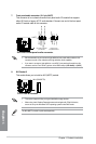
• ATXpowerbutton/soft-offbutton(2-pinPWR_BTN)
This connector is for the system power button. Pressing the power switch for more than
four seconds while the system is ON turns the system OFF.
• Resetbutton(2-pinRESET)
This 2-pin connector is for the chassis-mounted reset button for system reboot without
turning off the system power.
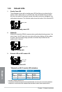
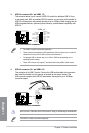
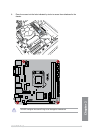
11. System panel connector (10-1 pin F_PANEL)
This connector supports several chassis-mounted functions.
Z97I-PLUS
Z97I-PLUS System panel connector
PIN 1
PWR_BTN
GND
PWR
PWR_LED-
PWR_LED+
(NC)
HWRST#
Ground
HDD_LED-
HDD_LED+
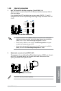
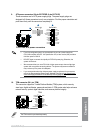
F_PANEL
+PWR LED-
+HDD_LED- RESET
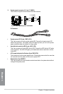
Q-Connector