© 2008 • All rights reserved. 9
DLA2/4/6 Speaker Level Audio Router
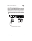
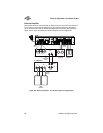
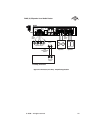
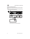
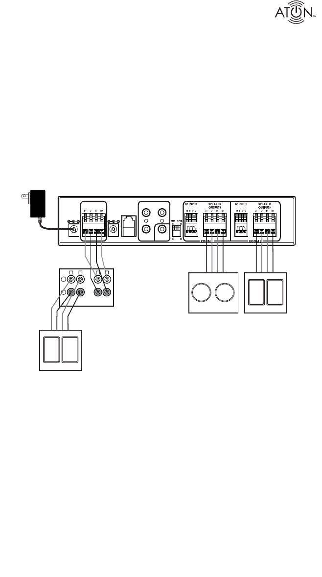
Zone 2 Output of an A/V or Stereo Receiver
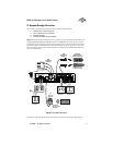
Certain A/V Receivers and Stereo Receivers have a Zone 2 feature that allows them to play
a seperate source to a second zone. Figure 2-3 shows the Zone 2 speaker outputs of an A/V
receiver connected to to the AMPLIFIER INPUT of the DLA2. Like the previous example, a pair
of speakers are connected to the DLA2s Room 1 Speaker Outputs, while an additional pair of
speakers is connected to the Room 2 Speaker Outputs. This application allows the A/V receiv-
er’s Main speakers to play in the room in which the receiver is located, while two additional
pairs of speakers play in other areas of the home. This is a multi-source application: the Main
speakers may play one source, while Zone 2 (the DLA2 locations) plays a different source.
Note: Set the Zone 2 volume level to the point where it achieves the maximum listenable
level (prior to distortion). The DLA2/4/6’s volume level will adjust up to this maximum
level.
IR EMITTER OUTPUTS
IMPEDANCE
MATCH
RF
INPUT
PATE NT
PENDING
PWR IN
12VDC / 2.1A
SENSE
INPUT
9VDC / 100mA
8
8
4 4
AMPLIFIER
INPUT
1
PAGE/DB
TRIG IN
DLA2
A/V Receiver
Room 1
Speakers
(Zone 2)
Room 2
Speakers
(Zone 2)
16/4
Speaker
Cables
16/4
Speaker
Cables
+
-
L
L
R
R
ZONE 1
ZONE 2
Main
Speakers
(Zone 1)
CLASS 2 WIRING
Figure 2-3: A/V Receiver Zone 2 Application


