


vii3550-A2-GB20-10 February 1995
Preface
About This Guide
This user’s guide provides the information needed to
install and operate your Model 3550 or 3551 data service
unit (DSU), which may or may not be equipped with a
dial backup module (DBM) or time division multiplexer
(TDM). If your DSU is not equipped with these options,
skip the information that pertains to them.
Be sure to read the safety and regulatory information at
the beginning of this guide.
It is assumed that you are familiar with the functional
operation of digital data communications equipment.
How to Use This Guide
This guide provides basic information about your DSU,
how to install it and verify that it is installed and operating
correctly, how to operate the unit and its options, and how
to configure it.
Two installation chapters are provided, one for the
Model 3550 DSU and one for the Model 3551 DSU.
Select the chapter that applies to your DSU.
Refer to the following chapters or appendices, as
needed.
Chapter 1 Provides a general overview of the
DSU and its options, information
about equipment upgrades and
conversions, and the unit’s technical
specifications. It also includes
equipment warranty information and
equipment return instructions.
Chapter 2 Provides step-by-step instructions for
installing your standalone
Model 3550 DSU.
Chapter 3 Provides step-by-step instructions for
installing your carrier-mounted
Model 3551 DSU.
Chapter 4 Describes how to operate your DSU
and its DBM and TDM/Flex options.
Chapter 5 Presents the basics of setting and
changing configuration options, and
provides Configuration Option Set
Tables, which describe each
configuration option in an option set,
along with its possible settings.
Appendix A Provides a diagram for navigating
the DSU’s menu structure.
Appendix B Summarizes the configuration option
sets for you.
Appendix C Lists the DSU’s status indicators, as
well as their messages, identifying
when they appear.
Appendix D Shows point-to-point and multipoint
application configurations and
network hookups.
Appendix E Provides cable and connector pin
assignments.
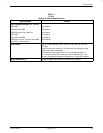
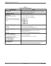
Appendix F Equipment List
Glossary
Reference Card