


COMSPHERE 3550 Series Data Service Units
3-8 February 1995 3550-A2-GB20-10
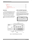
Power-Up Routine
When power is applied, the DSU:
• Determines what options (DBM or TDM/Flex) are
installed, if any.
• Runs a Device Test on itself and each of the
installed options.
During the tests, all indicators on the DCP light
briefly and the message Power-Up Tests appears on
the liquid crystal display (LCD).
• Displays the results of each test momentarily as
Pass, Fail, or Abrt. (Abrt indicates that the Device
Test was aborted because a network loopback was
in progress during the power-up procedure.) These
tests take about 20 seconds to complete.
If a TDM/Flex is installed, MUX is displayed as
Pass or Fail.
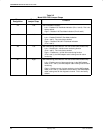
If the DSU or DBM fails this test, follow the procedure
below. Refer to Appendix A as you perform the
procedures described in this guide. Refer to Chapters 4
and 5 for additional examples and procedures.
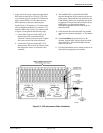
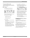
Procedure
1. Press the
key to return to the top-level menu.
2. Select Local (F1 key).
3. Press the
key to scroll the Confg
(Configuration) branch into view.
4. Press the function key directly below Confg.
5. Press the F1 key to select Opts (Configuration
Options).
The Load from screen appears.
6. Press the
key to bring the factory-loaded unit
configurations into view, and select the
appropriate configuration.
• PTPC for a point-to-point control
• PTPT for a point-to-point tributary
• MPTC for a multipoint control
• MPTT for a multipoint tributary
7. Press the F1 key to SAVE the selected
configuration.
The Save to screen appears.
8. Save the selected configuration to Activ
(F1 key).
9. Press the
key to return to the top-level menu,
then select Local again.
10. Select the Test branch (F3).
The Run Test on screen appears.
11. Select the device that Failed: the DSU (or the
TDM/Flex) or DBM.
12. Press the F2 key to run the Device Test again.
The device should pass.
13. Should the device fail, return the unit to the
AT&T Paradyne Repair Center (see Chapter 1).
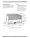
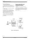
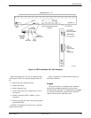
Connecting to the Network
Network connections are provided through the
3000 Series Carrier. Refer to Figure 3-2 as you read the
following sections and set up your network connections.
Connecting to the NMS
A Model 3551 DSU is set up for network diagnostic
connection through the shared diagnostic unit (SDU),
which is installed in Slot 0 of the carrier. Refer to the
COMSPHERE 3000 Series Carrier, Installation Manual
to set up the network diagnostic connection.
For connection of the DSU, see Appendix E of this
guide. For pin assignments, see Appendix D.
Connecting to the
Dial (or PSTN) Network
Connection to the dial network (or public switched
telephone network – PSTN) for the carrier-mounted
Model 3551 DSU is through a network interface module
(NIM) that is installed onto the carrier’s backplane (see
Figure 3-2). Refer to the COMSPHERE 3000 Series
Carrier, Installation Manual for additional information or
to install the NIM.