


Configuring the Unit
5-253550-A2-GB20-10 February 1995
Table 5-11
(3 of 4)
MUX (Port) Configuration Options*
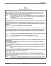
TxCarrSel: Const
Next Const Cntrl Prev
Transmitter Carrier Select
(only displayed when Full Mode is enabled). Enables the TDM/Flex transmitter circuitry to
simulate switched-carrier operation (using the V.13 codes) on an individual channel. Simulated switched-carrier
operation is also referred to as pseudo-controlled carrier (PCC) mode. It is required for applications where the receiving
DTE expects a raised LSD lead prior to receiving data.
NOTE: A port may be configured for switched-carrier operation in one direction and constant-carrier operation in the
other.
Const — Select (constant-carrier operation) if the V.13 codes are not to be sent. The corresponding remote
TDM/Flex port must be configured for Receiver Constant Carrier or Mark (
RxCarrSel
set to Const or
Mark). Configure each port in a digital-sharing group for Constant Carrier operation (
TxCarrSel
set to
Const).
Cntrl — Select Controlled or switched-carrier operation (PCC mode) if the DSU is to transmit the V.13 codes over
the DDS line when the port RTS changes state. When RTS is turned ON, the DSU transmits a code that
turns ON LSD at the remote TDM/Flex port before CTS is turned ON at the local port. When RTS is
dropped, the DSU sends a code that turns Off LSD at the remote TDM/Flex port. The corresponding
remote TDM/Flex port must be configured for Receiver Controlled Carrier (
RxCarrSel
set to Cntrl). This
selection is not valid if the DSU is part of a Digital-Sharing Device (DSD) group. (See the Mark selection
in the configuration option Receiver Carrier Select.)
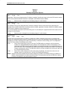
RxCarrSel: Const
Next Const Cntrl Mark Prev
Receiver Carrier Select
(only displayed when Full Mode is enabled). Enables the TDM/Flex receiver circuitry to simulate
switched-carrier operation (using the V.13 codes) on an individual circuit.
NOTE: Configuration values Const and Cntrl for Receiver Carrier Select are both valid choices for a port belonging to a
digital-sharing group.
Const — Select Constant-carrier operation if the receiving DSU is not to look for V.13 codes used by the V.13
protocol, and is not to toggle LSD.
Cntrl — Select Controlled or switched-carrier operation (PCC mode) if the receiving DSU is to look for V.13 codes
used by the V.13 protocol indicating the transition of RTS at the remote TDM/Flex port; the receiving DSU
toggles LSD as appropriate.
Mark — Select if 30 consecutive Marks are received and received Line Signal Detect (LSD) goes Off at the port.
Received LSD goes ON again just before the first space. (
TxCarrSel
must be set to Const at the remote
unit.)
This setting is used primarily when the remote DSU has a DSD group.
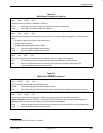
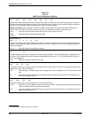
PCC Buffer: Disab
Next Enab Disab Prev
Pseudo-Controlled Carrier Buffer
(only displayed when Full Mode is enabled). Intercepts the V.13 codes used by the
V.13 protocol so they do not pass to the receiving DTE. This configuration option is only valid when
RxCarrSel
is set to
Cntrl.
For an asynchronous port configured for switched-carrier operation, set
PCC Buffer
to Enab.
For a synchronous port configured for switched-carrier operation,
PCC Buffer
can be disabled or enabled, depending on
whether the V.13 codes disrupt communication at the receiving DTE.
Be aware that enabling this configuration option
can corrupt the end-of-message for some synchronous protocols.
Enab — Select to enable the PCC Buffer feature.
Disab — Select to disable the PCC Buffer feature.
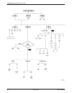
* The menu paths for Prt1 and Prt2 are identical.