


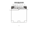
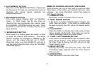
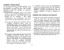
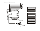
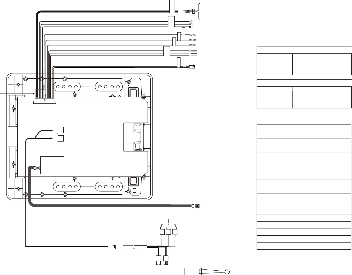
TYPICAL SYSTEM CONNECTIONS
-12-
1
2
3
4
5
6
12
10
7
8
9
15
16
17
13
14
T
O
F
M
T
R
A
N
S
M
I
T
T
E
R
S
P
E
A
K
E
R
O
R
H
E
A
D
P
H
O
N
E
C
O
N
N
E
C
T
I
O
N
L
I
N
E
O
U
T
-
R
L
I
N
E
O
U
T
-
V
L
I
N
E
O
U
T
-
L
T
W
O
D
O
M
E
L
I
G
H
T
’
S
C
O
N
N
E
C
T
I
O
N
P
O
W
E
R
(
+
1
2
V
)
P
O
W
E
R
(
G
N
D
)
White RCA(Audio Left)
Red RCA(Audio Right)
Y
ellow RCA(Video)
4 PIN
Power
Connector
2 PIN IR
Connector
A
ccessor
Harness
18
11
PIN 2
–
Power GND/Black
PIN 3
–
Dome Light ON
–
Red/Black
PIN 4
–
Lamp Common
–
Black/Red
PIN 5
–
Dome Light Auto
–
Purple/Brown
PIN 6
–
Line Out (L)/White
PIN 7
–
Spk Out (R) /Green
PIN 8
–
Spk Out-GND/Black
PIN 9
–
Spk Out (L)/Grey
PIN 10
–
Video Out/Yellow
PIN 11
–
Video GND/Black
PIN 12
–
Line Out (R)/Red
PIN 13
–
Power 12V(FM Trans.)/Red
PIN 14
–
Power GND (FM Trans.)/Black
PIN 15
–
Audio (L) Out (FM Trans.)/White
PIN 16
–
Audio GND (FM Trans.)/Black
PIN 17
–
Audio (R) Out (FM Trans.)/Red
PIN 18
–
Line Out GND/Black
PIN 1
–
Power/Red
Lamp Auto Purple/Brown
Constant 12V Black/Red
Lamp ON
Red/Black
Negative Dome Light Switching
Lamp Auto
Purple/Brown
Ground Black/Red
12Vdc Red/Black
Positive Dome Light Switching
IR Transmitter LED