


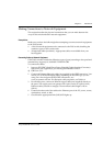
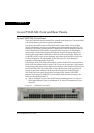
Chapter 6 Avaya P334T-ML Front and Rear Panels
Avaya P334T-ML User’s Guide 31
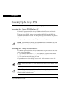
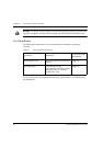
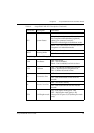
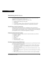
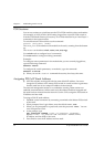
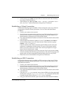
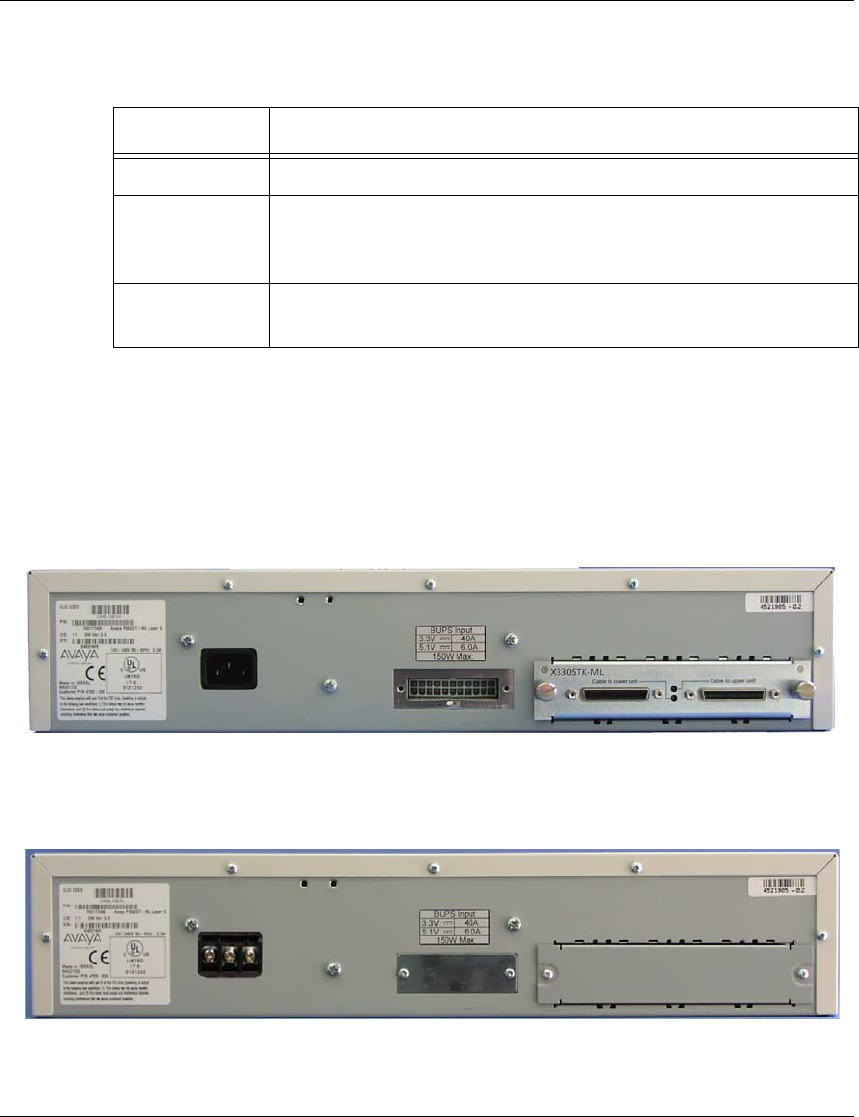
Avaya P334T-ML Back Panel
The P334T-ML back panel contains a Stacking Sub-module slot, power supply and
BUPS-ML connector. Figure 6.3 shows the back panel of the AC version switch and
Figure 6.4 shows the back panel of the DC version switch with a stacking sub-
module installed.
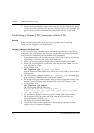
Figure 6.4 P334T-ML AC version Back Panel (with Stacking Sub-module,
BUPS-ML connector cover plate removed)
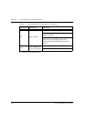
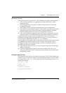
Figure 6.5 P334T-ML DC Back Panel (without Stacking Sub-module installed,
BUPS-ML connector cover plate shown)
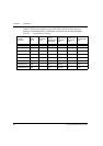
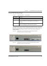
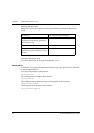
Table 6.2 Avaya P334T-ML <- -> Select buttons
Description Function
Left/Right Individual – select LED function (see table above)
Reset module Press both right and left buttons together for approximately 2
seconds. All LEDs on module light up until buttons are
released.
Reset stack Press both Right and Left buttons together for 4 seconds. All
LEDs on stack light up until buttons are released.