


12 OutLook ES Series Installer/User Guide
To install a 4- or 8-port switch:
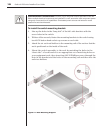
1. Prepare the location for the switch. See Rack Mounting your OutLook ES
Unit in this chapter if you are rack mounting the unit.
2. Select cables with appropriate connectors and length. (See Appendix B for
cable specications.)
NOTE: Cable length affects video quality as well as keyboard and mouse data timing. The
maximum cable length is determined in part by the computer and peripherals used. Not all
systems will give satisfactory results at the maximum length.
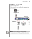
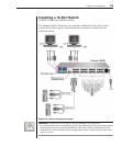
3. Connect the mouse, video and keyboard cables to the appropriate switch
connectors. Note that all keyboard and mouse cables are 6-pin miniDIN
PS/2 style and all the video cables are 15-pin VGA/SVGA style. (These
connectors are located on the left rear of the switch unit, with additional
connectors on the front of the OutLook 280 unit.)
NOTE: Keyboard and mouse connectors on the OutLook switch work with cables that have a
locking mechanism. The cable lock prevents cables from becoming disconnected from the switch
connectors due to the weight of the cable bundles or accidental tension from handling cables.
4. Select the computer that is to be connected to Port 1. Attach the computer’s
mouse to the appropriate connector on Port 1. Attach the computer’s monitor
to the 15-pin VGA connector. Attach the computer’s keyboard to the
appropriate connector. Bundle and label the cables for easy identication.
5. Repeat step 4 for all remaining computers to be connected to the switch unit.
6. Connect the power cord to the switch unit.