52 DSR Switch Installer/User Guide
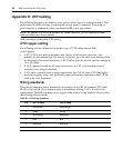
Appendix D: UTP Cabling
The following information is intended to brief you on various aspects of connection media. The
performance of a DSR switching system depends on high quality connections. Poor quality or
poorly installed or maintained cabling can diminish DSR system performance.
NOTE: This appendix is for information purposes only. Please consult with your local code officials and/or
cabling consultants prior to any installation.
DSR switching systems utilize UTP cabling.
UTP copper cabling
The following are basic definitions for the three types of UTP cabling that the DSR
switch supports:
• CAT 5 UTP (4-pair) high performance cable consists of twisted pair conductors, used
primarily for data transmission. The twisting of the pairs gives this cable some immunity from
the infiltration of unwanted interference. CAT 5 cable is generally used for networks running at
10 or 100 Mbps.
• CAT 5E (enhanced) cable has the same characteristics as CAT 5, but is manufactured to
somewhat more stringent standards.
• CAT 6 cable is manufactured to tighter requirements than CAT 5E cable. CAT 6 has higher
measured frequency ranges and significantly better performance requirements than CAT 5E
cable at the same frequencies.
Wiring standards
There are two supported wiring standards for 8-conductor (4-pair) RJ-45 terminated UTP cable:
EIA/TIA 568A and B. These standards apply to installations utilizing CAT 5, 5E and 6 cable
specifications. The DSR switching system supports either of these wiring standards. Please refer to
the following table for details.
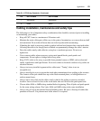
Table D.1: UTP Wiring Standards
Pin EIA/TIA 568A EIA/TIA 568B
1 white/green white/orange
2 green orange
3 white/orange white/green
4 blue blue
5 white/blue white/blue
6 orange green


