


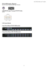
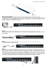

8/16 PS/2 KVM over IP switch
1
1. The Quick Installation Guide
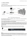
Installation
PS/2 IP-KVM switch redirects local keyboard, mouse and video data to a remote administration
console. All data is transmitted via IP. PS/2 IP-KVM switch can be used in a multi administrator and
multi server environment as well. Besides, PS/2 IP-KVM switch is a KVM switch, which can also be
used with a local console. Connecting PS/2 IP-KVM switch to the host system
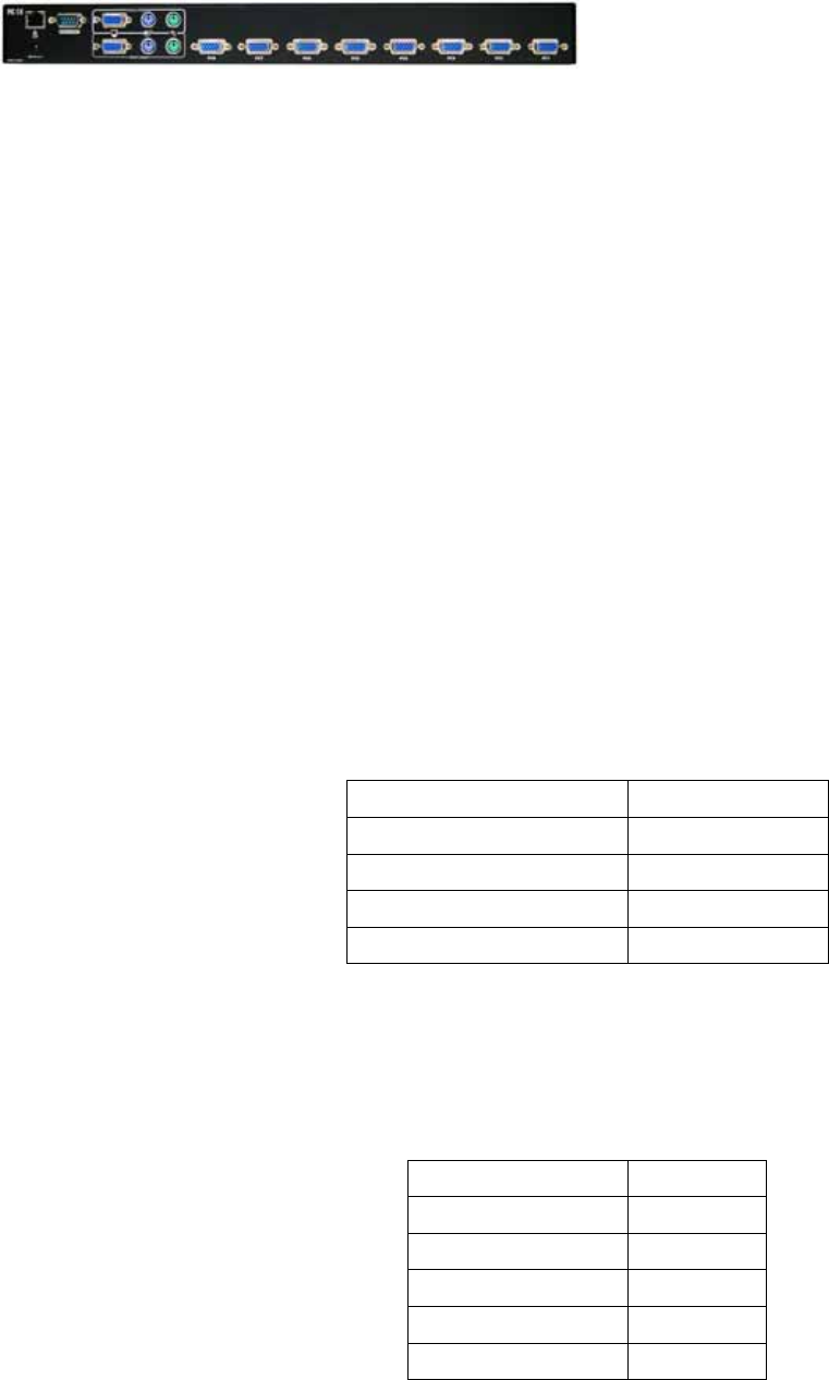
In order to connect the PS/2 IP-KVM switch perform the following steps:
1. Connect the power supply to PS/2 IP-KVM switch.
2. Connect the monitor to the PS/2 IP-KVM switch.
3. Connect the keyboard to the PS/2 IP-KVM switch.
4. Connect the mouse to the PS/2 IP-KVM switch.
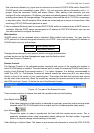
5. Plug the HDDB15 pin connector of a 3-in-one cable into any label computer port on the rear of
PS/2 IP-KVM switch unit. Then connect the HDDB-15 pin male type for PC video, the purple Mini
Din 6 pin female type for keyboard and the green Mini Din 6 pin female type for mouse. To plug
these three connectors into the respective ports of computer.
6. Repeat item 5 procedure to all of PC ports of PS/2 IP-KVM switch
7. Connect Ethernet and/or modem, depending how you want to access PS/2 IP-KVM switch.
Video modes
PS/2 IP-KVM switch recognizes a limited number of common video modes. When running X-Window
on the host system, please don’t use any custom mode lines with special video modes. If done so,
PS/2 IP-KVM SWITCH may not be able to detect these. You are on the safe side with all standard
VESA video modes. Please refer to Appendix C for a list of all known modes.
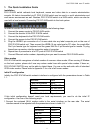
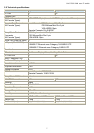
Initial IP configuration
Initially the PS/2 IP-KVM switch network interface is configured with the parameters shown in Table
1.1.
Parameter Value
IP auto configuration DHCP
IP-Address 192.168.1.22
Net-mask 255.255.255.0
Default-Gateway none
Table 1.1: Initial configuration
If this initial configuration doesn’t meet your local requirements, you need to do the initial IP
configuration. Use one of the following ways:
1.Connect the enclosed NULL modem cable to the serial interface on the rear side. The serial
interface needs to be adjusted with the parameters shown in table 1.2:
Parameter Value
Bits/second 115200
Data bits 8
Parity No
Stop bits 1
Flow Control None
Table 1.2: Serial parameters