


Installation 3-5
1-15HP Size A and B Controls
Dual
Expansion Board Installation
(Continued)
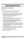
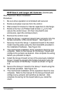
13.
The mechanical installation of the first expansion board is
now complete. Refer to the manual for the Group 2 board
and configure any jumpers and switches as desired. Also
complete the wiring for this board before you install the
cover.
14.
When complete, install the control cover using the four (4)
Phillips head screws.
15.
Restore all power sources to the control.
16.
Restore drive operation.
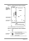
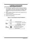
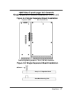
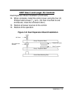
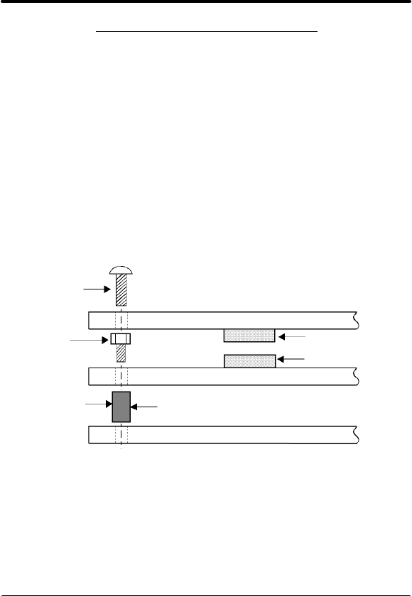
Figure 3-3 Dual Expansion Board Installation
#6 Screw
Female Connector
Male Connector
Group 2 Expansion Board
Group 1 Expansion Board
Main Circuit Board
Female/Female shown. Use Male/Female
in place of (MH1) screw (Figure 3-1).
Short
Aluminum
Standoff
Long
Aluminum or
Nylon Standoff