


3-6 Installation
15HP Size C and Larger AC Controls
(For
all 15H Inverter, 21H Line Regen Inverter
, 18H V
ector
, 22H
Line Regen V
ector and 23H Servo).
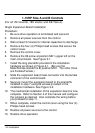
Single Expansion Board Installation
Procedure:
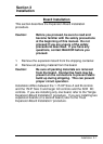
1.
Be sure drive operation is terminated and secured.
2.
Remove all power sources from the control.
3. W
ait at least 5 minutes for internal capacitors to discharge.
4.
Remove the four (4) Phillips head screws (
1
/
4
turn) that
secure the control cover
. (On floor mounted G size
enclosures, open the enclosure door).
5.
Remove the control cover
.
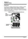
6.
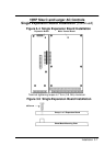
Slide the expansion board male connector into the female
connector of the control board. See Figure
3-4.
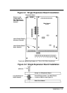
7.
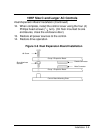
Securely mount the expansion board to the sheet metal
mounting plate using the #6 screws provided in the
installation hardware. See Figure 3-5.
8.
The mechanical installation of the expansion board is now
complete. Refer to Section 4 of this manual and configure
the jumpers as desired. Also complete the wiring before
you proceed to step 9.
9.
When complete, install the control cover using the four (4)
Phillips head screws (
1
/
4
turn). (On floor mounted G size
enclosures, close the enclosure door).
10.
Restore all power sources to the control.
11.
Restore drive operation.