


Setup 4-3
Connections
W
ARNING:
High voltage is present on the Resolver to
Digital expansion board. Do not touch any
circuit board, power device or electrical
connection before you first ensure that
power has been disconnected and there is
no high voltage present from this equipment
or other equipment to which it is connected.
Electrical shock can cause serious or fatal
injury. Only qualified personnel should
attempt the start-up procedure or
troubleshoot this equipment.
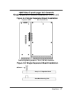
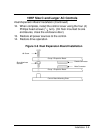
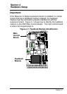
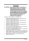
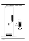
Procedure: (Refer to Figure 4-1 and FIgure 4-2.)
1.
Connect the resolver SINE+ wire to J1 terminal 51 of the
Resolver to Digital expansion board.
2.
Connect the resolver SINE– wire to J1 terminal 52 of the
Resolver to Digital expansion board.
3.
Connect the resolver COS+ wire to J1 terminal 53 of the
Resolver to Digital expansion board.
4.
Connect the resolver COS– wire to J1 terminal 54 of the
Resolver to Digital expansion board.
5.
Connect the resolver REFERENCE+ wire to J1 terminal 55
of the Resolver to Digital expansion board.
6. Connect
the resolver REFERENCE– wire to J1 terminal 56
of
the
Resolver to Digital expansion board.
7. Connect cable shields to J1 terminal 56 of the Resolver to
Digital expansion board. Shields are to be connected at the
expansion
board. (Shields not connected at the Resolver).
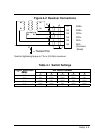
8.
Refer to T
able 4-1 and set the DIP switches for the
resolution you require.