


4-2 Setup
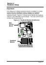
If
your V
ector control does not look like the one pictured in Figure
4-1, do not perform the feedback module removal procedure.
Instead, continue onto page 4-3.
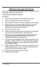
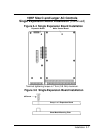
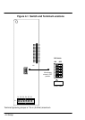
Feedback Module Removal Procedure
If your V
ector control looks like the one pictured in Figure 4-1,
perform the following procedure:
The resolver feedback module must be removed from the main
control board to change the JP1 position. Use the following
procedure.
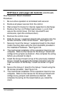
1.
Be sure drive operation is terminated and secured.
2.
Remove all power sources from the control. W
ait at least 5
minutes for internal capacitors to discharge.
3.
Remove the control cover
.
4.
Use a grounded wrist strap connected to chassis ground.
5.
Firmly grasp the Resolver Feedback Module and remove it
from its connectors on the main control board. Be careful
not to bend the pins by twisting or lifting the module
unevenly.
6.
Place the Resolver Feedback Module in an antistatic bag
and store it in a clean area for future use.
7.
Install the control cover
.
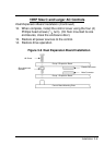
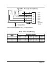
Now there is no conflict between this module and the Resolver to
Digital expansion board signal inputs to the control board. The
Resolver to Digital expansion board will provide the input signals
for the control board to use. Continue on page 4-3.