


Location and Function of Controls
2-1
5975977 BARCODATA 708 260597
2
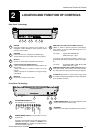
LOCATION AND FUNCTION OF CONTROLS
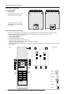
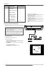
Rear Panel Terminology
3
4
5
6 7
8
2
1
COMM PORT
(800 p eripherals)
REMOTE
RG(S)B
S
VIDEO
S-VIDEO
R-Y Y(S) B-Y
RS232OUTRS232IN
IR
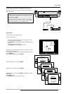
RS232IN
Connection between the projector and an IBM PC (or
compatible) or MAC (RS422) for remote computer control
and data communication.
RS232OUT
Used to connect to the next projector, RS232IN plug
(communication link for PC or MAC to the next projector)
IR sensor
receiver for control signals transmitted from the RCU.
Communication port (800 peripherals)
* allows communication between the RCVDS switcher and
the projector.
* allows connection of a remote IR receiver unit to the
projector.
* allows connection of an IRIS 800 to converge the image
automatically.
IR Remote
remote input for wired remote control
3
4
2
1
5
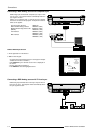
RGB-S IN or (R-Y)Y(B-Y)-S IN (4x BNC connector):
RGB-S in
: allows a character generator, microcomputer,
video camera, etc. having analog RGB output to be con-
nected to the projector.
Line inputs: - signals RED-GREEN-BLUE
- COMPOSITE sync. signal
(R-Y)Y(B-Y)-S IN
(component in):allows to connect e.g. a
professional VCR having component outputs to the projec-
tor.
Line inputs - signals RED-LUMA, LUMA, BLUE-LUMA
- COMPOSITE sync. signal
VIDEO IN (Composite video, 1x BNC connector): allows a
video tape recorder, video camera, color receiver/monitor,
etc. having video line output to be connected to the projector.
S-VIDEO IN: Separated Y/C (luma-chroma) signal inputs
and outputs for higher quality playback of Super VHS signals
(4-pin S-VIDEO connector).
7
6
8
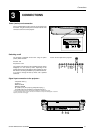
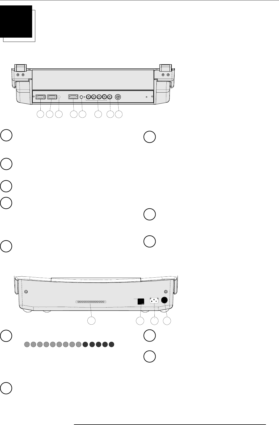
Front Panel Terminology
2
3 4
1
1
AUTODIAGNOSIS DISPLAY
LED indication for service purposes.
POWER (MAINS) SWITCH : press the switch to turn the
projector ON.
Depending on the hardware set-up of the projector during
installation, the projector switches to
‘standby’ or to
‘operational mode’. If in standby, the standby led in the
autodiagnosisdisplay lights up.
-9V
HOLD DOWN HD
COINC
SF
HOLD DOWN EHT
STANDBY
-CONV
-17V
+17V
+HTHD
+CONV
+9V
+210V
+30V
2
3
4
POWER (MAINS) INPUT: Connect the supplied ac power
(mains) cord here and to wall the outlet.
IR SENSOR
receiver for control signals transmitted from the RCU700.