


Location and Function of Controls
2-1
5975628 BARCOGRAPHICS 1209S 010797
2
V NOM
I MAX
FREQ
120/230 Volt
7/5Amp
50/60Hz
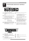
LOCATION AND FUNCTION OF CONTROLS
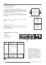
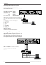
REAR PANEL TERMINOLOGY
Communication Port (800 peripherals)
* allows communication between the RCVDS switcher and
the projector.
* allows connection of a remote IR receiver unit to the
projector.
Port 3
RGB Analog Input (9 pin female sub D connector). Allows
a character generator, microcomputer, etc. having analog
RGB outputs to be connected to the projector.
Port 4/5 : RGB-S Input (5x BNC connector):
RGB-S input : allows a character generator, microcom-
puter, video camera, etc. having analog RGB output to be
connected to the projector.
Line inputs: - signals RED-GREEN-BLUE
- COMPOSITE sync. signal
- Tri level sync signal (option)
VIDEO Input (Composite video, 2x loop-through BNC
connector): allows a video tape recorder, video camera,
color receiver/monitor, etc. having video line output to be
connected to the projector.
75 ohm Termination Switch for Video signals
1
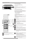
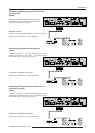
FRONT PANEL TERMINOLOGY
RS 232 Input Port
Connection between the projector and an IBM PC (or
compatible) or MAC (RS422) for remote computer control
and data communication.
RS 232 Output Port
RS 232 Input Port allows a communication link for PC or MAC
to the next projector in a series of projector.
IR Sensor
receiver for control signals transmitted from the RCU.
IR Remote
Connector for remote input for hard wired remote control
AC Power input
2
3
4
5
6
1
2
3
4
5
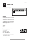
Projector Pilot Lamp : indicates the status of the projec-
tor.
- unlit : mains (power) switch is not pressed.
- lit : mains (power) switch is pressed and the indicated
color shows the projector mode:
Green color : operational mode of the projector.
Red color : standby mode of the projector.
Important : projector ("Operational" or "Standby") mode is
defined during the installation of the projector. (Refer to a
qualified technician for change).
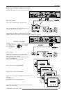
S-VIDEO Input: S-Video or Video in, depending on the
priority setting in the Picture Tuning menu.
For S-Video : Separated Y/C (luma-chroma) signal inputs
and outputs for higher quality playback of Super VHS
signals (4-pin S-VIDEO connector loop-through).
75 ohm Termination Switch for S-Video signals
For Video : Composite video inputs on pin 1 and 3.
Power Switch : press the switch to turn the projector ON.
Depending on the hardware set-up of the projector during
installation, the projector switches to Standby or to
Operational' mode. If in standby, the standby LED lights
up.
7