


DS-RPC OWNER’S MANUAL
CABLING
__________________________________________________________________________________________
14
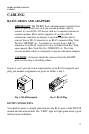
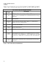
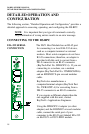
Tables 2 and 3 define the pin layout for the DS71 or DS71-MD2 and DS74.
DS71 EIA-232 RJ-45 Pin/Signal Definition
Pin EIA-232
Signal
Description
1 Handshake
Out
(DTR) Line Driver Inactive State = High: +12V when power is
applied. Used as a handshake line to enable/disable the receiving of
characters.
2 Gnd Signal ground
3 Handshake
Out
(RTS) Line Driver Inactive State = High: +12 V when power is
applied. Not used to enable/disable.
4 TX Out Transmit Data (data out)
5 RX In Receive Data (data in)
6 Handshake
In
(DSR) Handshake In. –12V when not used.
7 Gnd or
DCD In
Signal ground when Jumper JP6-2 is connected to JP6-3. In order
for the DS71 to take advantage of “DCD Logon/Logoff” and “Auto
Connect Port”, Jumper JP6-2 is connected to JP6-1 providing DCD
In.
8 Handshake
In
(CTS) Used as a handshake line to enable/disable the receiving of
characters.
Table 2 DS71 PIN SIGNAL DEFINITION