


6
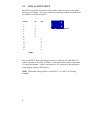
3.2 PDI-2 AC INPUT SETUP
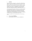
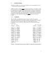
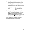
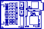
The PDI-2 module has two banks of dip switches which are used to add ripple
filtering for AC inputs. AC input is selected by individual channel. Location of the
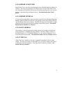
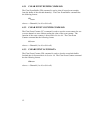
dip switches is shown in Figure 3.
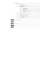
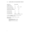
CHANNEL SW1 SW2
1 1
2 2
3 3
4 4
5 5
6 6
7 7
8 8
9 1
10 2
11 3
12 4
13 5
14 6
15 7
16 8
Table 1
Dip switch SW1 1-8 provides filtering control for channels 1-8 while SW2 1-8
controls channels 9-16. Refer to Table 1 to determine which switch corresponds
to a particular channel. A port is configured for AC operation by positioning the
corresponding switch to ON position.
NOTE: The default setting for SW 1-8 and SW2 1-8 is "OFF" (AC filtering
disabled).
Figure 3