


18
The following examples show the messages received using data commands where
the PDI is installed in Unit 1 Module 15 with time tagging enabled. If you select
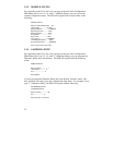
the module and issue the RD1<cr> command (Report Event Duration for Channel
1), the module will respond with a single message showing the Event Duration for
Channel 1 similar to the following:
1:15,1 1320 11/18/93 09:12:22
where 1:15,1 represents Unit 1/Module 15/Channel 1, 1320 indicates the event
duration is 1320 milliseconds, and 11/18/93 09:12:22 is the time tag.
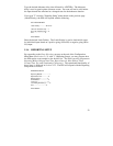
If you issue the RC1<cr> command (Report Event Counter for Channel 1), the
module will respond with a message showing the Event Counter similar to the
following:
1:15,1 823 11/18/93 09:12:22
where 1:15,1 represents Unit 1/Module 15/Channel 1, 823 indicates the number of
recorded events is 823 times, and 11/18/93 09:12:22 is the time tag.
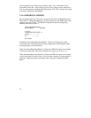
If you issue the RS1<cr> command (Report Single Buffered Event for Channel 1),
the module will respond with a message showing the input status for Channel 1
similar to the following:
1:15,1 1 11/18/93 09:12:22
where 1:15,1 represents Unit 1/Module 15/Channel 1, 1 indicates the first buffered
sample for Channel 1 is closed (PDI-1) or has voltage applied (PDI-2), and
11/18/93 09:12:22 is the time tag.