


5
3 INSTALLATION
The PDI-1 and PDI-2 are installed in the M Series chassis as described in Section
3.5 of the base unit operator's manual.
NOTE: The PDI-1 or PDI-2 cannot be installed as Module 1. If an PDI-1 or PDI-
2 is removed from a module slot and a different PDI-1 or PDI-2 is installed in that
location, the newly installed module acquires the previous module's configuration.
Moving an PDI-1 or PDI-2 to a different module location requires reconfiguration
because the configuration parameters are stored as a function of slot location and
module type. The configuration information does not stay with a relocated
module.
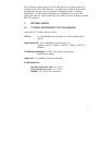
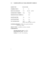
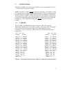
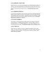
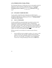
3.1 CABLING
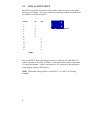
The V79 PDI-1 and V80 PDI-2 modules each have a DC-37F connector.
Equipment connections for each module is similar. Each input of the V79 module
has a ground connection and each input of the V80 module has a return
connection. Figure 1 and Figure 2 below show the V79 and V80 connections
respectively.
Circuit Pin # Circuit Circuit Pin # Circuit
Connection Connection Connection Connection
Input #1
1 20
Ground #10 Input #1
1 20
Return #10
Ground #1
2 21
Input #11 Return #1
2 21
Input #11
Input #2
3 22
Ground #11 Input #2
3 22
Return #11
Ground #2
4 23
Input #12 Return #2
4 23
Input #12
Input #3
5 24
Ground #12 Input #3
5 24
Return #12
Ground #3
6 25
Input #13 Return #3
6 25
Input #13
Input #4
7 26
Ground #13 Input #4
7 26
Return #13
Ground #4
8 27
Input #14 Return #4
8 27
Input #14
Input #5
9 28
Ground #14 Input #5
9 28
Return #14
Ground #5
10 29
Input #15 Return #5
10 29
Input #15
Input #6
11 30
Ground #15 Input #6
11 30
Return #15
Ground #6
12 31
Input #16 Return #6
12 31
Input #16
Input #7
13 32
Ground #16 Input #7
13 32
Return #16
Ground #7
14 33
N.C. Return #7
14 33
N.C.
Input #8
15 34
N.C. Input #8
15 34
N.C.
Ground #8
16 35
N.C. Return #8
16 35
N.C.
Input #9
17 36
N.C. Input #9
17 36
N.C.
Ground #9
18 37
N.C. Return #9
18 37
N.C.
Input #10
19
Input #10
19
Figure 1
: V79 Input Connections: V79 Input Connections
Figure 2
: V80 Input Connections: V80 Input Connections