


Documentation Number 3PCISD4x-3903 Manual Appendix A A-1
B&B Electronics Mfg Co – 707 Dayton Rd - PO Box 1040 - Ottawa IL 61350 - Ph 815-433-5100 - Fax 815-433-5104
B&B Electronics Ltd – Westlink Comm. Pk. – Oranmore, Galway, Ireland – Ph +353 91-792444 – Fax +353 91-792445
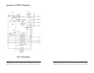
Appendix A: DB9 Signal Connections
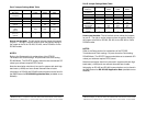
With 2-wire RS-485 mode operation, your connection cable must
jumper RD(A) to TD(A) and RD(B) to TD(B). Connect from TD(A) &
TD(B) to the Data A(−) and Data B(+) wires of your RS-485 network.
The EIA RS-422 Specification labels data lines with an "A" and "B"
designator. Some RS-422 equipment uses a "−" and "+" designator.
In almost all cases, the "A" line is the equivalent of the "−" line and
the "B" line is the equivalent of the "+" line. See our RS-422/485
Application Note (available on our websites).
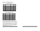
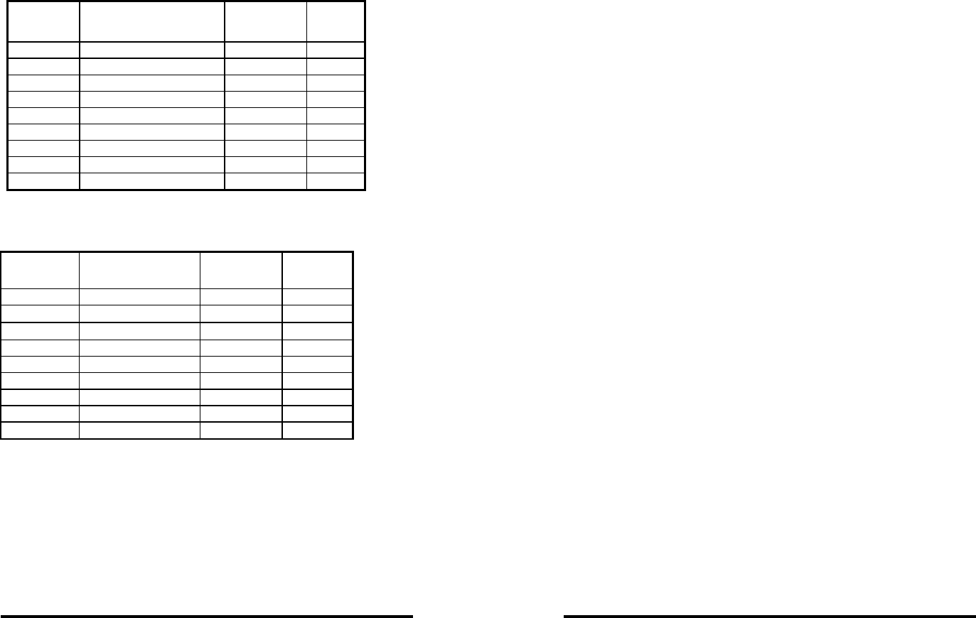
Table 7: RS-232 Pinouts
RS-232
Signal
Description Direction DB9M
Pin
DCD Data Carrier Detect input 1
RD Receive Data input 2
TD Transmit Data output 3
DTR Data Terminal Ready output 4
GND Signal Ground ---- 5
DSR Data Set Ready input 6
RTS Request to Send output 7
CTS Clear to Send input 8
RI Ring Indicator Input 9
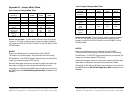
Table 8: RS-422/RS-485 Pinouts
RS-422
signal
Description Direction DB9M
Pinout
-- -- 1
RD(A) −
Receive Data A input 2
TD(A) −
Transmit Data A output 3
-- -- 4
GND Signal Ground ---- 5
-- -- 6
TD(B) + Transmit Data B output 7
RD(B) + Receive Data B input 8
-- NA 9
A-2 Appendix A Documentation Number 3PCISD4x-3903 Manual
B&B Electronics Mfg Co – 707 Dayton Rd - PO Box 1040 - Ottawa IL 61350 - Ph 815-433-5100 - Fax 815-433-5104
B&B Electronics Ltd – Westlink Comm. Pk. – Oranmore, Galway, Ireland – Ph +353 91-792444 – Fax +353 91-792445