


Documentation Number 3PCISD4x-3903 Manual Appendix B B-1
B&B Electronics Mfg Co – 707 Dayton Rd - PO Box 1040 - Ottawa IL 61350 - Ph 815-433-5100 - Fax 815-433-5104
B&B Electronics Ltd – Westlink Comm. Pk. – Oranmore, Galway, Ireland – Ph +353 91-792444 – Fax +353 91-792445
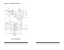
Appendix B: Jumper Mode Tables
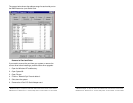
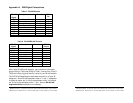
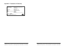
Port A Jumper Settings Mode Table
Jumpers
Port A (1)
RS-232 RS-422
4-wire
RS-485
4-wire
RS-485
2-wire
JP1
(4 Jumpers)
232 422 422 422
JP3A MODE 232 422/485 422/485 422/485
JP3B RX not used 422 422 485
JP3C TX not used 422 485 485
JP3D (SD/RTS)
(typical)
not used not used RTS/SD
SD
RTS/SD
SD
JP3E - Term
120Ω (typical)
not used IN/OUT
OUT
IN/OUT
OUT
IN/OUT
OUT
JP5 Clock
(x4 or x1)
(typical)
*4/*1
*1
*4/*1
*1
*4/*1
*1
*4/*1
*1
How to use the table: The left vertical column shows the jumpers
for port A. The right 4 vertical columns show the position setting of
the jumper at the left for RS-232, RS-422 or 4-wire RS-485 or 2-wire
RS-485 modes.
NOTES:
Refer to the Setup section for explanations of the RTS/SD,
Termination and Clock settings. All ports share the Clock setting.
RS-485 Mode: The SD/RTS jumpers should be set to automatic SD
unless your software requires RTS Control.
Note that termination should only be used in systems with both high
baud rates (>19200) and over several thousand feet of cable.
Information on RS-422 and RS-485 communications can be found in
the B&B Electronics RS-422/485 Application Note (available on our
Website).
B-2 Appendix B Documentation Number 3PCISD4x-3903 Manual
B&B Electronics Mfg Co – 707 Dayton Rd - PO Box 1040 - Ottawa IL 61350 - Ph 815-433-5100 - Fax 815-433-5104
B&B Electronics Ltd – Westlink Comm. Pk. – Oranmore, Galway, Ireland – Ph 353-91-792444 – Fax 353-91-792445
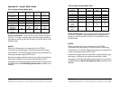
Port B Jumper Settings Mode Table
Jumpers
Port B (2)
RS-232 RS-422
4-wire
RS-485
4-wire
RS-485
2-wire
JP2
(4 Jumpers)
232 422 422 422
JP4A MODE 232 422/485 422/485 422/485
JP4B RX not used 422 422 485
JP4C TX not used 422 485 485
JP4D (SD/RTS)
(typical)
not used not used RTS/SD
SD
RTS/SD
SD
JP4E - Term
120Ω
(typical)
not used IN/OUT
OUT
IN/OUT
OUT
IN/OUT
OUT
JP5 Clock
(x4 or x1)
(typical)
*4/*1
*1
*4/*1
*1
*4/*1
*1
*4/*1
*1
How to use the table: The left vertical column shows the jumpers
for Port B. The right 4 vertical columns show the setting of the
jumper at the left for RS-232, RS-422 or 4-wire RS-485 or 2-wire
RS-485 modes.
NOTES:
Refer to the Setup section for explanations of the RTS/SD,
Termination and Clock settings. All ports share the Clock setting.
RS-485 Mode: The SD/RTS jumpers should be set to automatic SD
unless your software requires RTS Control.
Note that termination should only be used in systems with both high
baud rates (>19200) and over several thousand feet of cable.
Information on RS-422 and RS-485 communications can be found in
the B&B Electronics RS-422/485 Application Note (available on our
Website).