


Documentation Number 3PCISD4x-3903 Manual Chapter 2 7
B&B Electronics Mfg Co – 707 Dayton Rd - PO Box 1040 - Ottawa IL 61350 - Ph 815-433-5100 - Fax 815-433-5104
B&B Electronics Ltd – Westlink Comm. Pk. – Oranmore, Galway, Ireland – Ph +353 91-792444 – Fax +353 91-792445
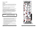
RS-232 Mode
To configure Port 1 for RS-232 mode, 5 jumpers must be checked.
The following settings will configure Port 1 as RS-232.
1. Set the four jumpers of JP1 to the "232" (left) position.
2. Set the first jumper of JP3 (A) to the "232" (left) position.
The remaining jumpers of JP3 are unused in the RS-232 mode and
may be in either position.
RS-422 Mode
Nine jumpers must be set/checked to configure each Port to the
RS-422 mode. To set Port 1 for RS-422, set as follows below:
1. Set the four jumpers on JP1 to the "422" (right) position.
2. Set the top jumper of JP3 (A) to the "422/485" (right) position.
3. Set the second and third jumpers of JP3 (B) & (C) to the "422"
(right) position. (These constantly enable receive & transmit.)
4. The fourth jumper JP3 (C) is unused in the RS-422 mode.
(Selects RTS/SD for 485 mode)
5. The bottom jumper of JP3 (E) switches the 120Ω receiver
termination resistor IN or OUT. Typically this resistor is not used.
In some cases using high baud rates and very long cables,
termination is needed. See our RS-422/485 Application Note.
6. Configure each port as above using the table in Appendix B.
Table 7: RS-232 Pinouts
RS-232 Signal Description Direction DB9M Pin
DCD Data Carrier Detect input 1
RD Receive Data input 2
TD Transmit Data output 3
DTR Data Terminal Ready output 4
GND Signal Ground ---- 5
DSR Data Set Ready input 6
RTS Request to Send output 7
CTS Clear to Send input 8
RI Ring Indicator Input 9
8 Chapter 2 Documentation Number 3PCISD4x-3903 Manual
B&B Electronics Mfg Co – 707 Dayton Rd - PO Box 1040 - Ottawa IL 61350 - Ph 815-433-5100 - Fax 815-433-5104
B&B Electronics Ltd – Westlink Comm. Pk. – Oranmore, Galway, Ireland – Ph +353 91-792444 – Fax +353 91-792445
RS-422/RS-485 Pinouts
The RS-422 mode supports 2 channels (transmit and receive).
With 2-wire RS-485 mode operation, your connection cable
must jumper RD(A) to TD(A) and RD(B) to TD(B). Connect from
TD(A) & TD(B) to the Data A(−) and Data B(+) wires of your RS-485
network.
The EIA RS-422 Specification labels data lines with an "A" and
"B" designator. Some RS-422 equipment uses a "−" and "+"
designator. In almost all cases, the "A" line is the equivalent of the
"−" line and the "B" line is the equivalent of the "+" line. More
information on RS-422 communications can be found in our free RS-
422/485 Application Note (available on our websites).
RS-485 Mode
For a 4-wire RS-485 single master system, the card can be set as in
the RS-422 mode (full duplex, transmit & receive enabled).
Nine jumpers must be set/checked to configure each Port to the RS-
485 mode. To set Port 1 for RS-485, set as follows below:
1. Set the four jumpers on JP1 to the "422" (right) position.
2. Set the top jumper of JP3 (A) to the "422/485" (right) position.
3. For 2-wire mode, set the second jumper, JP3(B) to the "485"
(left) position (half duplex). For 4-wire mode, set it to the "422"
(right) position (full duplex, receive enabled).
4. Set the third jumper, JP3 (C) to the "485" (left) position.
Table 8: RS-422/RS-485 Pinouts
RS-422
Signal
Description Direction DB9M
Pinout
-- -- 1
RD(A) −
Receive Data A input 2
TD(A) −
Transmit Data A output 3
-- -- 4
GND Signal Ground ---- 5
-- -- 6
TD(B) + Transmit Data B output 7
RD(B) + Receive Data B input 8
-- NA 9