


Manual Documentation Number: EIR608-xSFP_0708m 7
B&B Electronics Mfg Co Inc – 707 Dayton Rd - PO Box 1040 - Ottawa IL 61350 - Ph 815-433-5100 - Fax 815-433-5104 – www.bb-elec.com
B&B Electronics – Westlink Commercial Park – Oranmore, Galway, Ireland – Ph +353 91-792444 – Fax +353 91-792445 – www.bb-europe.com
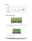
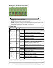
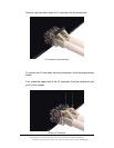
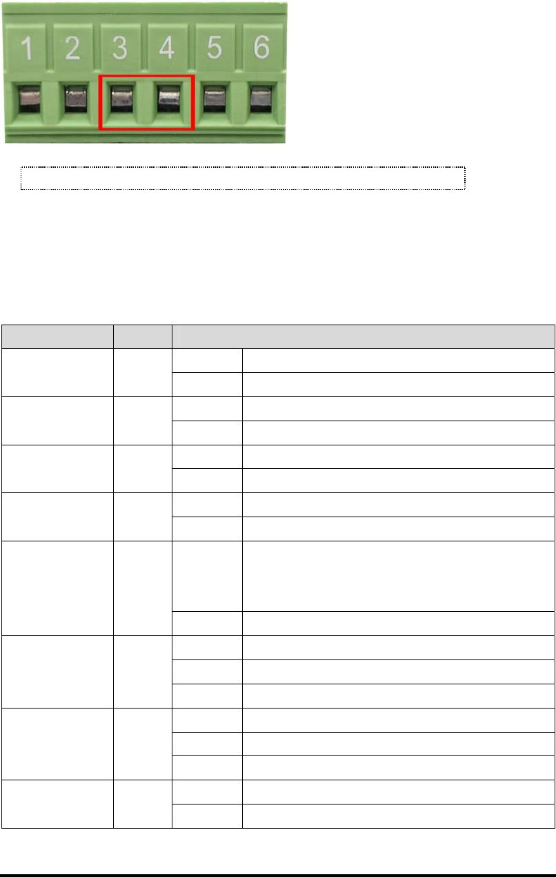
Wiring the Fault Alarm Contact
[NOTE] Use 12 to 24 AWG wire.
[NOTE] Relay contacts are normally closed.
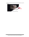
[NOTE] The Relay Alarm also requires software configuration. Refer to the
Web Based Management Fault Relay Alarm Section.
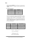
LED Indicators
LED Color Description
PWR Green
On System power on
Off No power inputs
R.M. Green
On The switch is the master of the X-ring group
Off The switch is not the master of the X-ring group
PWR1 Green
On Power input 1 is available
Off Power input 1 is not available
PWR2 Green
On Power input 2 is available
Off Power input 2 is not available
Fault Red
On
Power input 1 or 2 is off line or port link is down
See alarm setting for operational details
(depends on Fault Relay Alarm configuration)
Off Normal Operation
Link/Active
(P5 ~ P8)
Green
On SFP port linked
Flashing Data is transmitting or received
Off Not connected to network
P1 ~ P4
(Upper LED)
Green
On Connected to network
Flashing Networking is active at 100Mbps
Off Not connected to network
P1 ~ P4
(Lower LED)
Green
On Connected to network at 1000Mbps
Off Not connected to network
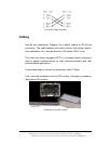
Insert the wires into the fault alarm contact
(
No. 3 & 4
)