


1-28 (No.PA019)
MEASUREMENT
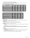
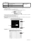
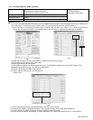
(1) Open the previously renamed Excel file and select the [PHS_Rch] sheet.
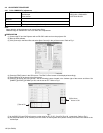
(2) Set the values of the [R[, [G] and [B] scroll bars to [0] in the [DDIC Control][Flat Field] tag in the [DDIC Control] screen.
(3) Set the slide switch to [FORWARD] on the Phase Deviation Measurement circuit.
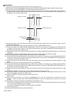
(4) Connect the Phase Deviation Measurement circuit probe to the 1st Phase pin, a header pin on the PCB to which the FPC is
connected. Enter the value measured on the Digital Voltmeter without a minus sign to [FORWARD ROTATION] [Black] [1], or
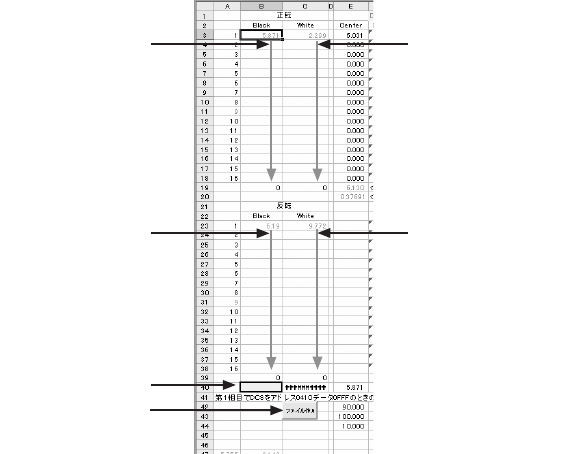
the [B3] cell in the Excel file. Refer to Fig.4.
Fig.4
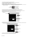
(5) Connect the probe to the 2nd Phase pin and enter the measured value to [B4]. Perform the procedure stated in step (4)
through to the 16th phase.
(6) Set the slide switch on the Phase Deviation Measurement circuit to [REVERSE ROTATION].
(7) Connect the probe of the Phase Deviation Measurement circuit to the 1st Phase pin, a header pin to which the FPCis
connected. Enter the value measured on the Digital Voltmeter without minus sign to [REVERSE ROTATION] [Black] [1], or
the [B23] cell in the Excel file. Refer to Fig.4.
(8) Connect the probe to the 2nd phase and enter the measure value to [B24]. Repeat the procedure from step (7) through to the
16th phase.
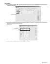
(9) Of the [R], [G] and [B] in the [Flat Field]tag, set the scroll bar value of the color to be measured to [1023].
(10) Set the slide switch on the Phase Deviation Measurement circuit to [FORWARD].
(11) Connect the Phase Deviation Measurement circuit probe to the 1st phase pin, a header pin on the PCB to which the FP1C is
connected. Enter the value measured on the Digital Voltmeter without a minus sign to [FORWARD ROTATION] [White] [1],
or the [C3] cell in the Excel file. Refer to Fig.4.
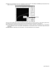
(12) Connect the probe to the 2nd Phase pin and enter the measured value to [C4]. Repeat the procedure through to the 16th
phase.
(13) Set the slide switch on the Phase Measurement circuit to [REVERSE].
(14) Connect the Phase Deviation Measurement circuit probe to the 1st phase pin, a header pin on the PCB to which the FPC is
connected. Enter the value measured on the Digital Voltmeter without a minus sign to [REVERSE ROTATION] [White] [1], or
the [C23] cell in the Excel file. Refer to Fig.4.
(15) Connect the probe to the 2nd Phase pin and enter the measured value to [C24]. Repeat the procedure through to the 16th
phase.
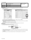
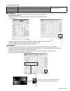
(16) In the [Flat Field][DDIC Control] screen, set all the [R], [G] and [B] scroll bar values to [0].
(17) Set [DCSDAT] of the color under measurement to [ON]. Enter the value measured on the Digital Voltmeter without a minus
sign to the cell [B40] in the Excel file. Refer to Fig.4.
(18) Press the [CREATE FILE] button located in [C42] in the Excel file.
Refer to Fig.4.
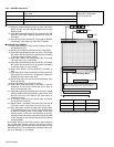
(19) Press the [Load File] button in the [DDIC Control][Register] tag. If the Rch measurement is performed, select the
[C:\FHD\~~~.txt] file and press [OK] in the [CONFIRM] message box. Be sure to modify the xxx in the file name to a serial
number.
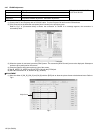
(20) Set [GINDAT], [SUPDAT], [DCSDAT] and [RVSDAT] to [ON]. Refer to Fig.4.
If the measured voltage differences on Phase 1 through to Phase 16 in the Phase Deviation Measurement circuit are within
+/-10 mV, the result is determined to be PASSED.
If the result is outside this range, the result is determined to be FAILED.
(21) Turn the Projector OFF.
(22) Perform the procedures from step (9) for Gch and Bch.
(4)Enter from here
(17)Enter here
(18)Click
(11)Enter from here
(7)Enter from here
(14)Enter from here