75
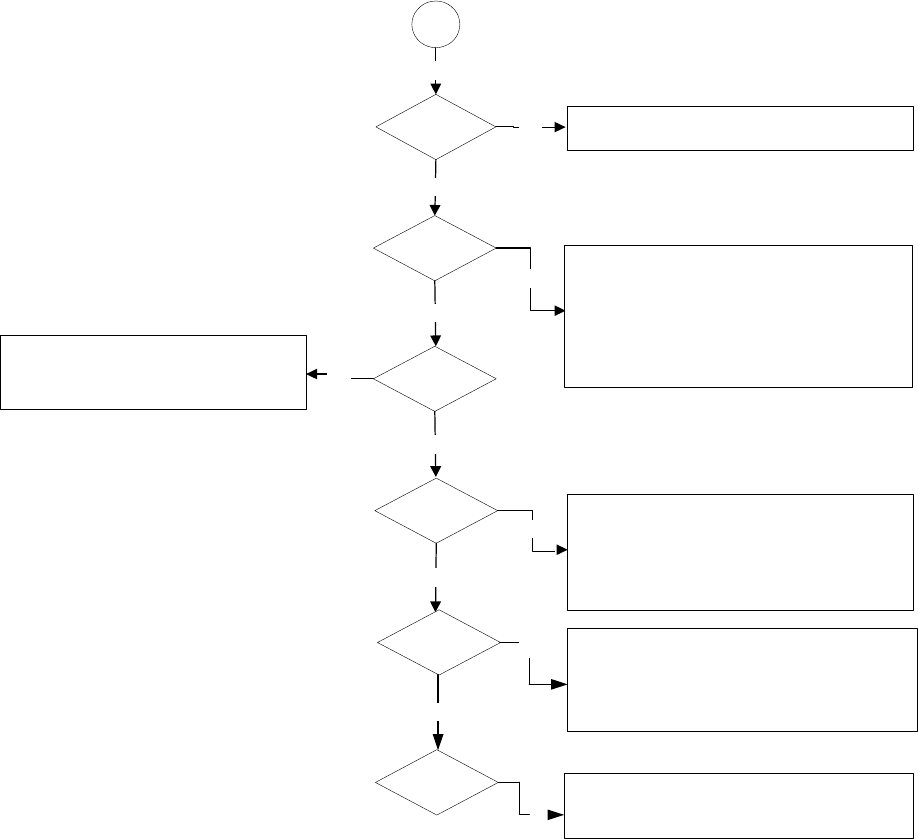
DMD Driver
Start
Power Voltage
Yes
No
Yes
DDP 1000
function
No
Yes
.
Peripheral
Hardware
Yes
No
Image Color
No
Yes
Image Quality
1.chk CW spinning in cloclwise
2.chk CW tape position and width
3.chk cutrain displayed 220us after CW index
4.sequence color transition during CW spoke interval
No
Lamp On
Yes
No
1.chk J702,2.5V(4,,5,6),5V(3),12V(1)
2.chk bead L710-L714,L44
1.chk clock frequency (unit:MHz)
a.Y901(30)b.Y5(20) C.UY1(100)
C.Motor Controller(8.33)
2.chk ACTDATA,POWERON,RESETZ,CLKIN,HSYNC,
VSYNC,SYNCVALID from Front End
3.chk CW spinning frequency 120Hz , if wrong, chk
MTRDATA , MTRCLK , MTRSELZ
1.LAMPEN Signal to Ballast.
2. 3.5s after LAMPLIT,DMD Become Active and
Display an Image .
1.Output from DAD1000 : VBIAS(22-25V),VRST(-26V),
VCC2(7.5V)
2.chk control signal of DMD chip from
U29(RN40,RN45)
3.chk data sequence from U29 to FPC(RN37~RN44)
4.chk JP2,JP3 soldering
1.chk CWINDEX
2.chk LAMPEN
3.chk LAMPLIT


