


5
®
SECT 3
Installation and operation
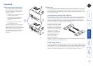
LOCAL module switches (continued)
LOCAL Switch 1
OFF: Normal operation.
ON: (Before power is applied) Places the LOCAL module into ash upgrade
mode so that the internal software can be changed. Please see the ‘Flash
upgrade’ section in the ‘Special conguration’ section.
ON: (Whilst power is applied) Places the REMOTE module into password
override mode. This allows any pre-congured passwords to be altered
- particularly useful when they have been lost or forgotten. Please see the
‘Password override’ section in the ‘Special conguration’ chapter.
LOCAL Switch 2
OFF: Normal operation.
ON: Set transparent mode. Use this setting if the Wizard extender modules are
to be used with KVM switches produced by other manufacturers. Cascaded
KVM switches often use special signals to set or identify conditions. In
transparent mode, the Wizard extender modules will pass the signals
without attempting to interpret them.
LOCAL Switch 3
OFF: Microphone input on REMOTE module. Use this setting if a standard
mono-channel microphone is connected to the MIC input on the REMOTE
unit.
ON: Stereo line-in input on REMOTE module. Use this setting if a stereo input is
applied to the MIC input on the REMOTE unit.
LOCAL Switch 4
OFF: Normal operation.
ON: Suspend operation and reset the LOCAL module. Use this setting
momentarily to produce the same effect as removing and restoring power
if incorrect operation has occurred. Return the switch to the OFF position
to allow normal operation to continue.
Installation
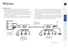
The installation of the Wizard extenders is straightforward and can best be
achieved in most cases by following these stages for each module:
• Stage A Check or set the conguration switch settings
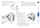
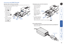
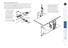
• Stage B Mount the module
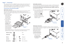
• Stage C Connect the cables
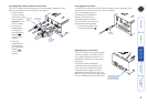
Stage A - Conguration switch settings
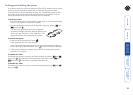
The basic operation of the LOCAL and REMOTE modules are controlled by the
banks of four switches located on the side of each module. The switches are
monitored at all times and may be changed when power is on or off (the only
exception to this rule is switch 1 of the LOCAL module which initiates slightly
different functions depending on the power state when it is switched).
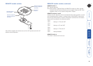
LOCAL module switches
OFF: Normal operation
ON: Transparent mode
OFF: Normal operation
ON: Flash upgrade/reset
password modes
OFF: Normal operation
ON: Reset LOCAL module
OFF: Microphone input mode
ON: Stereo line-in mode
Note: When shipped, all switches are set in the OFF positions and this will
produce normal operation with normal microphone input (at the REMOTE
module).
1
O
N
2
3
4
1
ON
4
2
3
ON