


9
CHAPTER 4: Option Selection
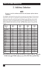
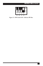
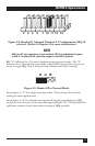
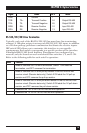
Figure 4-2. Header E1 Optional Windows 3.1 Configuration. IRQ 10
selected. (Refer to Chapter 6 for more information.)
NOTE
IRQ 2 on AT class machines is not available. IRQ 9 is substituted in place
of IRQ 2. To select IRQ 9, place the jumper on the IRQ 2 position.
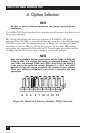
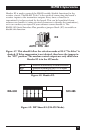
E2: “N” indicates the (N)ormal, single-interrupt-per-port mode. The “S”
indicates the (S)hared interrupt mode, which allows more than one port to
access a single IRQ. This is the preferred Windows and OS/2 setting.
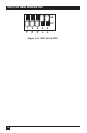
Figure 4-3. Header E2 in Normal Mode.
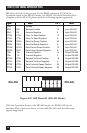
Set jumpers to “N” for single interrupt mode. This setting is the normal
setting for most applications.
Set jumpers to “S” for shared interrupt mode for all ports sharing an IRQ
except for one. Set one of the ports sharing an IRQ to “M.” This provides the
pull-down resistor circuit that makes sharing of IRQs possible.
N
S
M
31110 12 154275