


11
CHAPTER 4: Option Selection
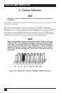
Header E3 is used to control the RS-485 enable/disable functions for the
receiver circuit. The RS-485 “Echo” is the result of connecting the board’s
receiver inputs to the transmitter outputs. Every time a character is
transmitted it is also received by the board. This can be beneficial if your
software can handle it (using received characters to throttle the transmitter),
or it can confuse your system if your software cannot handle it. The
RS422/485 Serial Interface Plus provides a jumper block (E3) to enable or
disable this function.
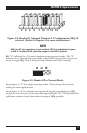
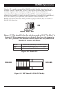
Figure 4-7. This should follow the selection made at E5 if “No Echo” is
desired. If Echo suppression is not desired, then leave the jumper in
the “422” position. The modem control outputs are only valid when
Header E3 is in the 422 mode.
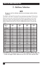
AUTO Receiver automatically Enabled/Disabled
RTS Receiver Enabled by UART RTS signal
422 Receiver always Enabled
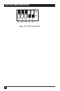
Figure 4-8. Header E3.
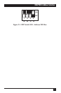
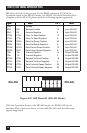
Figure 4-9. DIP Shunt E4 (EIA-530 Mode).
RTSAUTO
EIA-530 SIO-485
422
RX