


13
CHAPTER 4: Option Selection
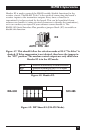
Signal Name Pin # Mode
GND Ground 7
TDB TX+ Transmit Positive 24 Output RS-422
TDA TX- Transmit Negative 25 Output RS-422
RDB RX+ Receive Positive 12 Input RS-422
RDA RX- Receive Negative 13 Input RS-422
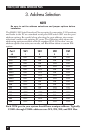
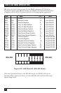
RS-530/422/485 Line Termination
Typically, each end of the RS-530/422/485 bus must have line-terminating
resistors. A 100-ohm resistor is across each RS-530/422/485 input, in addition
to a 1K ohm pull-up/pull-down combination that biases the receiver inputs.
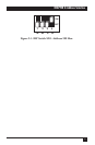
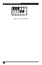
DIP switch SW2 allows you to customize this interface to your specific
requirements. Each switch corresponds to a specific portion of the interface.
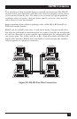
If multiple RS422/485 Serial Interface Plus adapters are configured in a
network, only the boards on each end should have switches 1, 2, and 3 ON.
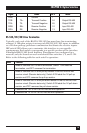
Refer to the following table for each switch’s operation:
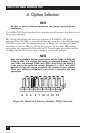
Name Function
T Adds or removes the 100-ohm termination. Switch 1 ON adds the
termination, and OFF removes the termination.
P Adds or removes the 1K ohm pull-up resistor in the RS-422/RS-485
receiver circuit (Receive data only). Switch 2 ON adds the 1K pull-up
resistor and OFF removes the pull-up resistor.
P Adds or removes the 1K ohm pull-down resistor in the RS-422/RS-485
receiver circuit (Receive data only). Switch 3 ON adds the 1K pull-down
resistor, and OFF removes the pull-down resistor.
L Connects the TX+ to RX+ for RS-485 two-wire operation.
L Connects the TX- to RX- for RS-485 two-wire operation.