


12
RS422/485 SERIAL INTERFACE PLUS
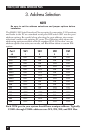
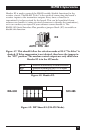
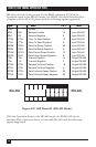
DIP shunt E4 selects the pin out for the DB25 connector P3. With the
5-position shunt in the EIA-530 mode, the RS422/485 Serial Interface Plus
complies with the EIA-530 pinout with the following signals supported:
Signal Name Pin # Mode
GND Ground 7
RDB RX+ Receive Positive 16 Input RS-422
RDA RX Receive Negative 3 Input RS-422
CTSB CTS+ Clear To Send Positive 13 Input RS-422
CTSA CTS- Clear To Send Negative 5 Input RS-422
DSRB DSR+ Data Set Ready Positive 22 Input RS-422
DSRA DSR- Data Set Ready Negative 6 Input RS-422
DCDB DCD+ Data Carrier Detect Positive 10 Input RS-422
DCDA DCD- Data Carrier Detect Negative 8 Input RS-422
TDB TX+ Transmit Positive 14 Output RS-422
TDA TX- Transmit Negative 2 Output RS-422
RTSB RTS+ Request To Send Positive 19 Output RS-422
RTSA RTS- Request To Send Negative 4 Output RS-422
DTRB DTR+ Data Terminal Ready Positive 23 Output RS-422
DTRA DTR- Data Terminal Ready Negative 20 Output RS-422
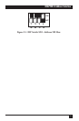
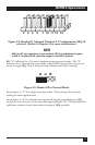
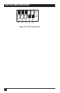
Figure 4-10. DIP Shunt E4 (SIO-485 Mode).
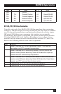
With the 5-position shunt in the SIO-485 mode, the RS422/485 Serial
Interface Plus converts to 4-wire or 2-wire RS-422/485 with the following
signals supported:
EIA-530
SIO-485