724-746-5500 | blackbox.com
Page 16
Chapter 2: Overview
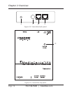
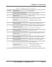
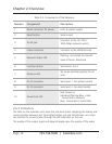
Table 2-2. Components of the Receivers.
Number Component Description
1 Barrel connector for power Links to power supply
2 Reset button System reset
3 RJ-45 jack
Connects to the 10-/100-/
1000-Mbps network switch
4 Video connector Connects to the HDMI monitor
5 Network Status LED
Flashing: Connected to network
Goes off once: Abnormal
6 Function button See Section 2.6.4.
7 Rotary switch
Set up an identical position for all
units
8 RJ-12 connector Serial port 1: For system control
9 RJ-12 connector Serial port 2: For data transfer
10 Power/Link LED
Red: Power on
Interlaced flashing Blue + Red:
Connected to network
Blue: Connected to transmitter
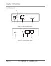
2.6.3 Indicators
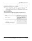
The LEDs on the extender units show the real-time status indicating the linking and
communication between the Transmitter/Sender unit and the Receiver unit. Users
can identify the current status through the LED indicators on the unit.
The quality of the output signal will depend largely upon the quality of the video


