


19
CHAPTER 3: Installation
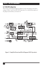
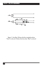
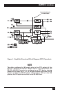
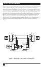
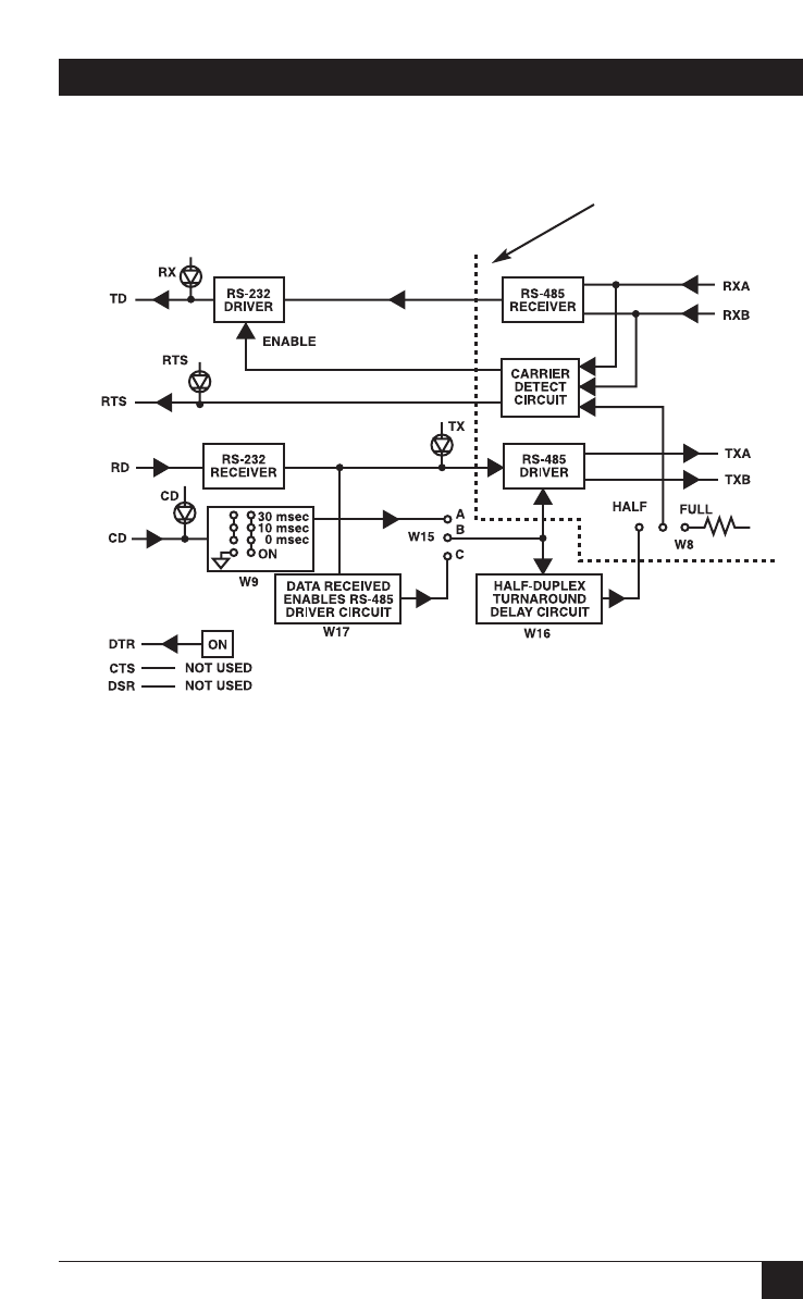
Figure 4. Simplified Functional Block Diagram (DTE Operation).
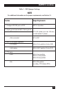
NOTE
The delay settings for W9 apply only to the CTS output of the
RS-232↔ 485/422 Converter. Since CTS is not used when the
RS-232↔485/422 Converter is configured as a DTE device, placing
jumper W9 in either the 0-, 10-, or 30-msec position will allow the CD
input to enable the RS-485 driver. When jumper W9 is in the ON
position, the CD input has no affect on the RS-485 driver.
Opto-isolated barrier
in IC109 models