


28
RS-232↔485/422 CONVERTERS
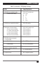
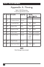
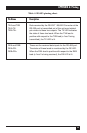
Appendix A. Pinning
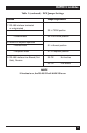
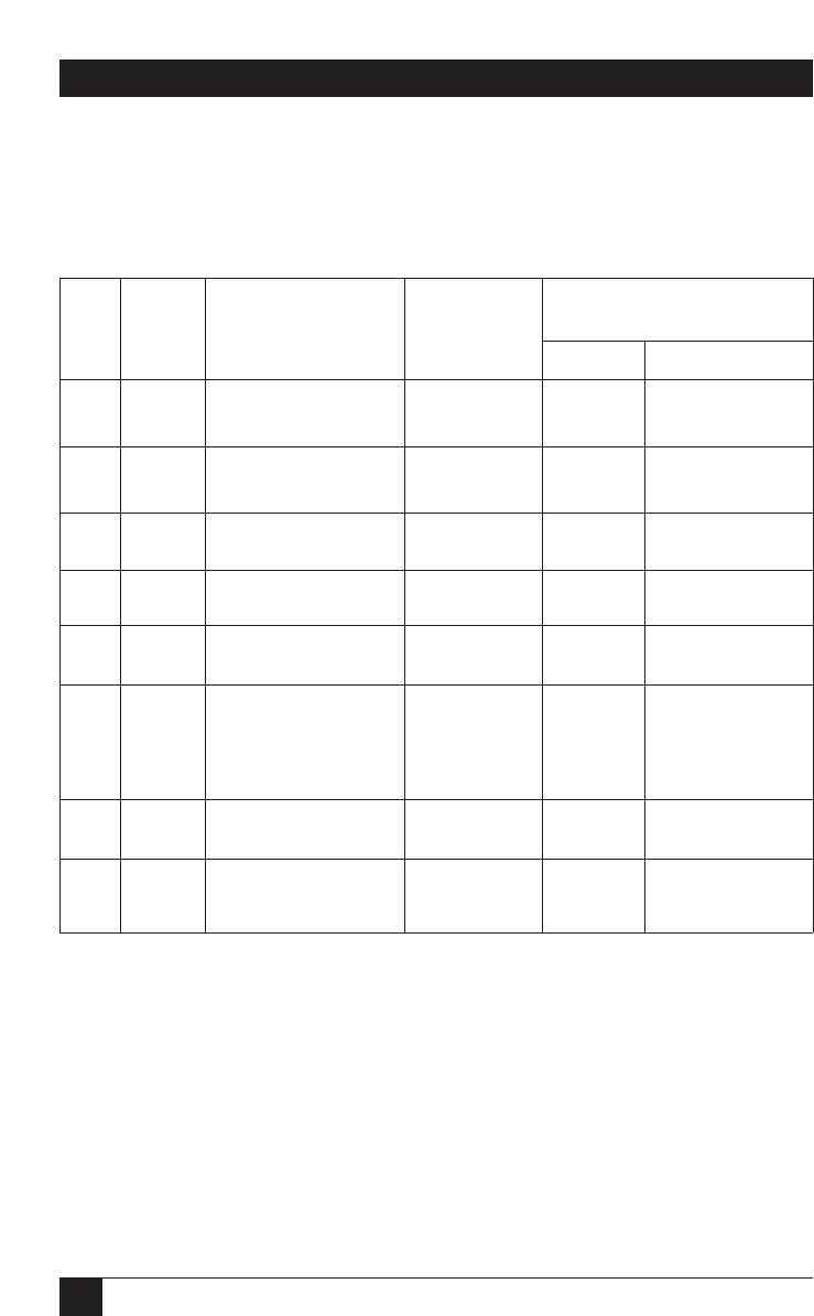
Table 3. RS-232 interface
(* denotes pins that are used).
Pin Circuit Description Signal Type Direction
when configured as
DCE DTE
1* AA Protective Ground Ground -
2* BA Transmitted Data Data Input Output
3* BB Receive Data Data Output Input
4* CA Request to Send Control Input Output
5* CB Clear to Send Control Output Not connected
6* CC Data Set Ready Control Output Not connected
(held
high)
7* AB Signal Ground Ground -
8* CF Data Carrier Detect Control Output Input
NOTE
Pins 9 through 25 are not used.