


V.35
↔
RS422 INTERFACE CONVERTER
10
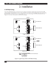
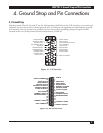
4.2 Pin Connections
Figures 4-1 and 4-2 show the pin connections for the V.35↔RS-422 Interface Converter. The illuminated
LEDs in these figures indicate incoming signals only.
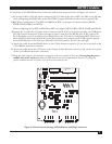
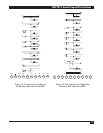
The unit is shipped without the jumper (Rx) between signal ground and chassis ground. The RS-422
port is configured DTE and the V.35 port is configured DCE.
For operation with the RS422 port as DCE and the V.35 port as DTE, the signal directions are reversed
1
.
Pins 12 and 30 of the RS422 port become inputs which are connected to a status LED.
1
In this configuration, W1 has no effect on the circuit W2 is used instead.
Pin 30
Pin H Pin 12
The unit is shipped with the TERMINAL READY jumper in the TRUE (ON) position.
AB - DTR passed through
BC - DTR always asserted
W2
A
B
C