


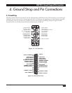


V.35
↔
RS422 INTERFACE CONVERTER
6
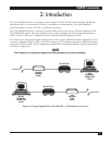
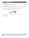
3. Installation
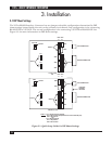
3.1 DIP Shunt Settings
The V.35↔RS-422 Interface Converter has two jumper selectable configurations determined by DIP
shunt settings located inside the unit on the printed circuit board. One configuration is for connecting
RS-422 DTE to V.35 DCE. The second configuration is for connecting V.35 DTE to RS-422 DCE. See
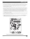
Figure 3-1 for more information on DIP Shunt settings.
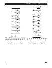
Figure 3-1. Quick Setup Guide for DIP Shunt Settings.
STEP 2
STEP 3
XW5
XW4
XW3
XW2
XW1
V.35 DTE
XW6
DTE
A
DCE
B
V.35 CONNECTOR
RS-422 CONNECTOR
If V.35 is DTE
OR
STEP 2
XW5
XW4
XW3
XW2
XW1
W2
A
B
C
W1
A
B
C
STEP 4
422 DTE
DTE
A
DCE
B
V.35 CONNECTOR
RS-422 CONNECTOR
If RS232 is DTE
XW6
W2
A
B
C
W1
A
B
C
STEP 4
STEP 1
STEP 1
STEP 3
STEP 4 Pin H Supported (As shipped)
W1 in BC Position (DTR passed from V.35 to RS-422 port)
W2 in AB Position
OR
Pin H Not Supported
W1 in AB position
W2 in BC Position
FACTORY
DEFAULT
SETTING