


CHAPTER 3: Installation
7
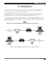
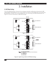
To install the V.35↔RS-422 Interface Converter, follow these steps and refer to Figures 3-1 and 3-2.
1. Set jumper XW6 to V.35 side when configuring the V.35 side of the unit as DTE. Set XW6 to the 422 side
when configuring the RS422 side of the unit as DTE. Jumper XW6 affects only the front panel LEDs.
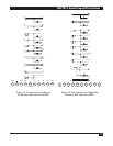
2 & 3. When configuring V.35 as DTE and RS-422 as DCE, set jumpers in sockets labeled XW1B,
XW2B, XW3B, XW4A, and XW5A.
When configuring V.35 as DCE and RS-422 as DTE, set jumpers XW1A, XW2A, XW3A, XW4B, and XW5B.
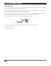
4. Jumper W1 is used if the V.35 side of the Converter is DCE. If W1 is in the B-C position, the DTR signal
(pin H) is passed from the V.35 port through to pins 12 and 30 of the RS-422 port. If W1 is placed in
the A-B position, pins 12 and 30 are forced high. When the V.35 side is configured as DTE, W1 has no
effect and W2 is used instead. With W2 in the A-B position, the terminal ready (DTR) signal is passed
from the RS-422 side of the V.35 port. With W2 in the B-C position, Pin H is forced high.
5. Attach the cable from the RS-422 device to the 37-pin female receptacle (J1) on the rear panel of the
V.35↔RS-422 Interface Converter.
6. Attach the cable from the V.35 device to the 34-pin female M-block connector (J2) on the rear panel
of the V,35↔RS-422 Interface Converter.
7. Plug the 4-pin power cord into the receptacle on the rear panel of the case. Do not plug the power
module into an AC outlet yet. After the DIP shunts are set as explained in Section 3.1, plug the
power module into an AC outlet. The unit is now ready to use.
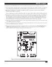
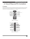
Figure 3-2. Board Layout Showing LED Indicators and Plug Connectors.
W2
W1
XW6
DTE DCE
J2
J1
RX
V.
3
5
RS
4
4
9