


Express Ethernet Switch LB9217A-R2 & Applicable Modules
10
o R
eset
B
utto
n
q P
o
r
t
Status
o
n
S
in
g
l
e
-P
o
r
t
M
odu
l
e
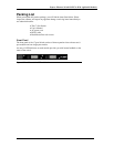
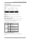
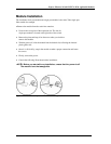
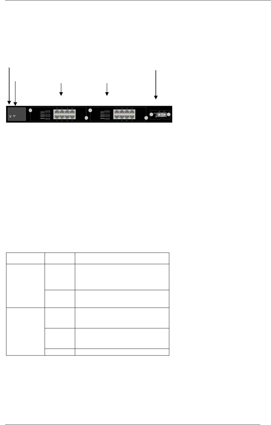
LEDs & Reset Button
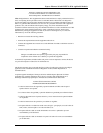
The array of LED indicators on the front panel conveys status and
configuration information to help you monitor and troubleshoot the
switch.
n Power
This LED comes on when the switch is connected to power and turned on.
o Reset Button
If the switch should become unresponsive, you may reset it by pressing this button.
p Port Status on 8-Port Modules
The front panel of the 17-Port Switch allows two 8-port modules. The ports numbered
from 1 to 8 on full TX module.
The LEDs are located at the left side of each section, displaying status for each
respective port. Please refer to Table 1 for more details.
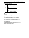
Table 1: Port Status
LED State Indication
Steady
A valid network connection
established.
LNK stands for LINK.
LNK/ACT
Flashing
Transmitting or receiving data.
ACT stands for ACTIVITY.
Steady
Connection in full duplex mode.
FDX stands for FULL-DUPLEX.
Flashing
Collision occurred.
COL stands for COLLISION.
FDX/COL
Off Connection in half-duplex mode.
q Port Status on Single-Port Module
A set of two LEDs conveys the port status on the single-port module. Consult Table 2
for details.
n P
ower
Z Port Status on 8-Port Modules